Maintenabce
and
Tr
oubleshooting
Maintenance
and
Tr
oubleshooting
8--16
Maintenance and Troubleshooting
DL105 PLC User Manual, 3rd Edition
There are many times, especially during machine startup and troubleshooting, that
you need the capability to force an I/O point to be either on or off. Before you use a
programming device to force any data type it is important you understand how the
DL105 CPUs process the forcing requests.
WARNING: Only authorized personnel fully familiar with the application
should make program changes. Do thoroughly consider the impact of any
changes to minimize the risk of personal injury or damage to equipment.
Bit Forcing —
Bit forcing temporarily changes the status of a discrete bit. For
example, you may want to force an input on even though the program has turned it
off. This allows you to change the point status stored in the image register. The
forced value will be valid until the CPU writes to the image register location during the
next scan. This is useful you just need to force a bit on to trigger another event.
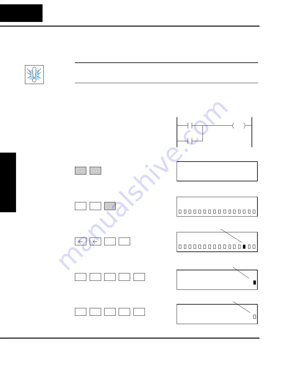
The following diagrams show a brief
example of how you could use the
D2--HPP Handheld Programmer to force
an I/O point. The example assumes you
have already placed the CPU into Run
Mode.
X0
Y0
OUT
C0
Use arrow keys to select point, then use
ON and OFF to change the status
SHFT
ON
INS
0
0
Y
1
Y
BIT REF
X
16P STATUS
From a clear display, use the following keystrokes
Use the PREV or NEXT keys to select the Y data type. (Once the Y
appears, press 0 to start at Y0.)
STAT
ENT
NEXT
0
A
ENT
Y2 is now on
0
0
Y
1
Y
Y7
BIT FORCE
From a blank display, use the following
keystrokes to force Y7 ON
Solid fill indicates point is on.
MLS
Y
7
H
SHFT
SHFT
ON
INS
Y7
BIT FORCE
From a blank display, use the following
keystrokes to force Y7 OFF
No fill indicates point is off.
MLS
Y
7
H
SHFT
SHFT
OFF
DEL
Forcing I/O Points
Bit Forcing with
Direct Access
Summary of Contents for DL105
Page 2: ...DL105 PLC User Manual Manual Number D1 USER M...
Page 308: ...1B DL105 Error Codes In This Appendix Error Code Table...
Page 314: ...1C Instruction Execution Times In This Appendix Introduction Instruction Execution Times...
Page 324: ...1D Special Relays In This Appendix DL105 PLC Special Relays...
Page 327: ...1E PLC Memory In This Appendix DL105 PLC Memory...


