Getting
Started
1--7
Getting Started
DL105 PLC User Manual, 3rd Edition
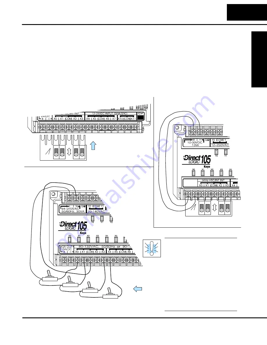
Step 2: Connect Switches to Input Terminals
To finish this quick-start exercise or study other examples in this manual, you’ll need
to connect some input switches as shown below. For most models, the F1-04SIM
Input Simulator is a quick way to install four switches on inputs X0 -- X3. DC-powered
units will require routing DC power to the simulator as shown. We recommend using
one of the models compatible with the input simulator as you learn the DL105.
However, you may wire individual toggle switches to AC-powered units as shown,
as
long as you follow the instructions in the accompanying WARNING note.
engineering
ON
OFF
FACTS
F1--04SIM
engineering
ON
OFF
FACTS
F1--04SIM
Slide simulator under
left-most terminals
and tighten screws.
F1--130DR--D, F1--130DD--D
(DC-powered versions)
F1--130DR/F1--130DR--CE,
F1--130DD/F1--130DD--CE,
F1--130DA
Toggle Switches, UL Listed
F1--130AR, F1--130AD, F1--130AA
(DC input versions)
(AC input versions, 120VAC only)
WARNING
:
DO NOT wire the
toggle switches as shown to
240VAC-powered
units.
The
discrete inputs will only accept
120VAC nominal. Also, remove
power and unplug the DL105
when wiring the switches. Only
use UL-approved switches rated
for at least 250VAC, 1A. Firmly
mount the switches before
using.
NEVER use the input simulator
on these units with AC-type
discrete inputs.
Summary of Contents for DL105
Page 2: ...DL105 PLC User Manual Manual Number D1 USER M...
Page 308: ...1B DL105 Error Codes In This Appendix Error Code Table...
Page 314: ...1C Instruction Execution Times In This Appendix Introduction Instruction Execution Times...
Page 324: ...1D Special Relays In This Appendix DL105 PLC Special Relays...
Page 327: ...1E PLC Memory In This Appendix DL105 PLC Memory...


