194
4317I–AVR–01/08
AT90PWM2/3/2B/3B
Note:
1. The example code assumes that the part specific header file is included.
For I/O Registers located in extended I/O map, “IN”, “OUT”, “SBIS”, “SBIC”, “CBI”, and “SBI”
instructions must be replaced with instructions that allow access to extended I/O. Typically
“LDS” and “STS” combined with “SBRS”, “SBRC”, “SBR”, and “CBR”.
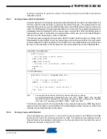
The function simply waits for data to be present in the receive buffer by checking the RXC flag,
before reading the buffer and returning the value.
18.7.2
Receiving Frames with 9 Data Bits
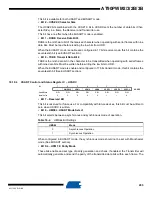
If 9-bit characters are used (UCSZ=7) the ninth bit must be read from the RXB8 bit in UCSRB
before reading the low bits from the UDR. This rule applies to the FE, DOR and UPE Status
Flags as well. Read status from UCSRA, then data from UDR. Reading the UDR I/O location will
change the state of the receive buffer FIFO and consequently the TXB8, FE, DOR and UPE bits,
which all are stored in the FIFO, will change.
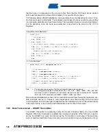
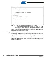
The following code example shows a simple USART receive function that handles both nine bit
characters and the status bits.
Assembly Code Example
(1)
USART_Receive:
;
Wait for data to be received
sbis
UCSRA, RXC
rjmp
USART_Receive
;
Get and return received data from buffer
lds
r16, UDR
ret
C Code Example
(1)
unsigned char
USART_Receive(
void
)
{
/*
Wait for data to be received
*/
while
( !(UCSRA & (1<<RXC)) )
;
/*
Get and return received data from buffer
*/
return
UDR;
}


