D 1.4 9
D_1
.4_0
1_G
B.
fm
9
-22
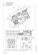
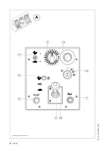
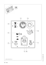
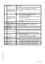
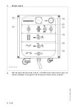
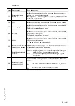
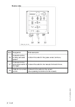
Item Designation
Brief description
16
(
o
)
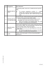
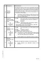
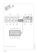
Reverse
selection
Feeder
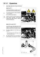
The transport direction of the conveyor, applicable separately
to both sides of the conveyor, can be switched to the opposite
direction so that over a short distance it retracts the material
directly before the auger. In this way the loss of material can
be avoided during transport. The conveyor travels about 1 m
in the direction of the hopper.
A
If necessary, press the button as many times as neces-
sary, so that the feeder operates in the opposite direc-
tion over a longer section.
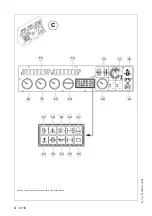
17
Conveyor
modes of opera-
tion on the right/left
sides
A - auto:
drive lever turned on and the material end posi-
tion switch provides continuous regulation in
the tunnel
B - stop:
turned off
C - manual:
continuously turned on (full delivery capacity,
(without material regulation)
- If the conveyor is to be remote controlled (
o
), then both
switches shall be set to „auto“ position.
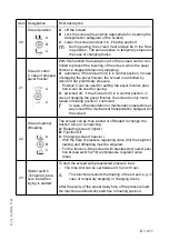
18
Tamper
(depends on the
screed)
A - auto:
drive lever turned on, in normal position turned
off
B - stop:
completely turned off
C - manual:
continuously turned on
Use „auto“ mode for laying in the basic case.
m
If the switch is in „manual“ position when laying, then it
must be set to „stop“ in normal position. In the opposite
case excessive tampering may take place.
A
Speed regulation (see „Operation manual of screed“)
19
Vibration
(depends on the
screed)
Operation and application similarly to the (tamper) switch.
A
Speed regulation (see „Operation manual of the
screed“).
B
C
A
A
B
C
A
B
C
Summary of Contents for DYNAPAC Svedala Demag DF 115 C
Page 2: ...VALUE QUALITY THE ORIGINAL Your Authorized Dynapac Dealer...
Page 10: ......
Page 18: ......
Page 20: ......
Page 44: ......
Page 58: ......
Page 62: ...D 1 4 4 D_1 4_01_GB fm 4 22 Element2_konv_Kette_635 bmp 9 12 9a 5 8 14 A 6 7 13...
Page 64: ...D 1 4 6 D_1 4_01_GB fm 6 22 Element2_konv_Kette_635 bmp 9 12 9a 5 8 14 A 6 7 13...
Page 96: ......
Page 120: ...D 4 6 24 D_4 6_01_GB fm 24 38 2 2 Error messages...
Page 121: ...D 4 6 25 D_4 6_01_GB fm 25 38...
Page 122: ...D 4 6 26 D_4 6_01_GB fm 26 38...
Page 123: ...D 4 6 27 D_4 6_01_GB fm 27 38...
Page 124: ...D 4 6 28 D_4 6_01_GB fm 28 38...
Page 125: ...D 4 6 29 D_4 6_01_GB fm 29 38 2 3 FMI codes...
Page 134: ......
Page 146: ...E 01 12 E_01_GB fm 12 18 3 Auger extension auger type II Auger_DEM bmp...
Page 152: ......
Page 154: ......
Page 157: ...F 3 0 1 F_3 0_01_GB fm 1 4 F 3 0 Maintenance Conveyor 1 Maintenance Conveyor...
Page 161: ...F 4 1 1 F_4 1_01_GB fm 1 8 F 4 1 Maintenance Auger 1 Maintenance auger sub unit...
Page 168: ......
Page 180: ......
Page 181: ...F 6 0 1 F_6 0_01_GB fm 1 8 F 6 0 Maintenance Hydraulic system 1 Maintenance hydraulic system...
Page 220: ......
Page 221: ...F 10 0 1 F_10 0_01_GB fm 1 6 F 10 0 Checks decommissioning 1 Tests check up cleaning stopping...
Page 226: ......

