D 4.6 36
D_4
.6_0
1_G
B.
fm
3
6
-3
8
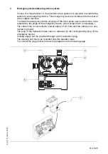
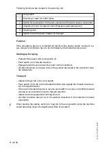
Following functions are located in the steering unit:
Function
If the emergency device is connected all functions like engine speed, conveyor, au-
ger, tamper and vibration have to be controlled by the forward reverse lever.
Starting up for laying
- Preselect the speed with turning knob (3)
- Push switch (2) in forward direction
- Engage forward reverse lever like under normal conditions
- All other functions (4, 5) have to be in the position described in the instruction man-
ual (Operation)
Transport
- Adjust turning knob (3) to a low speed
- Push switch (2) to the recommended direction and engage the forward reverse le-
ver to forward direction.
- If the recommended direction is reverse push switch in reverse, but still the forward
reverse lever should be moved to forward direction
- Adjust the driving speed with turning knob (3)
- All other functions have to be in the position described in the instruction manual
(Operation)
f
When starting the engine, switch (2) must be in the zero position since the machine
would otherwise move off straight away! Risk of accident!
Pos. Designation
1
Mounting screws for holder plate
2
Switch for preselection of the zero position and forward reverse movement
3
Adjustment knob for speed control (Replace speed preselector)
4
Steering knob
5
Switch to turn the paver finisher on the spot
Summary of Contents for DYNAPAC Svedala Demag DF 115 C
Page 2: ...VALUE QUALITY THE ORIGINAL Your Authorized Dynapac Dealer...
Page 10: ......
Page 18: ......
Page 20: ......
Page 44: ......
Page 58: ......
Page 62: ...D 1 4 4 D_1 4_01_GB fm 4 22 Element2_konv_Kette_635 bmp 9 12 9a 5 8 14 A 6 7 13...
Page 64: ...D 1 4 6 D_1 4_01_GB fm 6 22 Element2_konv_Kette_635 bmp 9 12 9a 5 8 14 A 6 7 13...
Page 96: ......
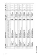
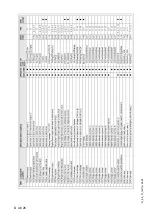
Page 120: ...D 4 6 24 D_4 6_01_GB fm 24 38 2 2 Error messages...
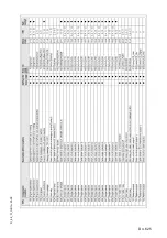
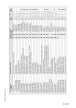
Page 121: ...D 4 6 25 D_4 6_01_GB fm 25 38...
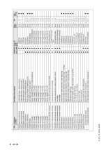
Page 122: ...D 4 6 26 D_4 6_01_GB fm 26 38...
Page 123: ...D 4 6 27 D_4 6_01_GB fm 27 38...
Page 124: ...D 4 6 28 D_4 6_01_GB fm 28 38...
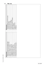
Page 125: ...D 4 6 29 D_4 6_01_GB fm 29 38 2 3 FMI codes...
Page 134: ......
Page 146: ...E 01 12 E_01_GB fm 12 18 3 Auger extension auger type II Auger_DEM bmp...
Page 152: ......
Page 154: ......
Page 157: ...F 3 0 1 F_3 0_01_GB fm 1 4 F 3 0 Maintenance Conveyor 1 Maintenance Conveyor...
Page 161: ...F 4 1 1 F_4 1_01_GB fm 1 8 F 4 1 Maintenance Auger 1 Maintenance auger sub unit...
Page 168: ......
Page 180: ......
Page 181: ...F 6 0 1 F_6 0_01_GB fm 1 8 F 6 0 Maintenance Hydraulic system 1 Maintenance hydraulic system...
Page 220: ......
Page 221: ...F 10 0 1 F_10 0_01_GB fm 1 6 F 10 0 Checks decommissioning 1 Tests check up cleaning stopping...
Page 226: ......

