AS64 series AC servo drive Function codes
-100-
3
If the zero speed clamp control signal is valid, the position control
mode is used when the actual motor speed becomes less than
P0.59 minus 10 r/min, and the servo is locked at this position.
Note:
⚫
After configuring any of parameters P3.00–P3.07 with the zero speed clamp (0x00D) function,
you can use the zero speed clamp terminals of the CN1 plug for control or use P4.19 [Zero
speed clamp command] for control. The input settings of P3.00–P3.07 are described as follows:
0: Disable zero speed clamp.
1: Enable zero speed clamp.
⚫
In torque control mode, the settings 0 and 1 are valid, and 2 and 3 have the same function as
1.
P0.58
Data size
16bit
Data format
DEC
Modbus address
1116, 1117
CANopen address
0x203A, 0x00
P0.59
Zero speed clamp
speed threshold
Setting range Default
Unit
Applicable
mode
10–20000
30
r/min
S
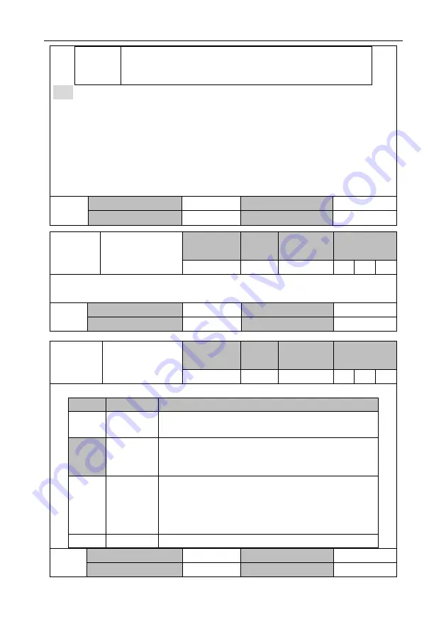
This parameter specifies the speed threshold for switching to position control when P0.58 is 2 or
3. When P0.58 is 3, there is a 10 r/min delay detected.
P0.59
Data size
16bit
Data format
DEC
Modbus address
1118, 1119
CANopen address
0x203B, 0x00
P0.60
Torque command
source
Setting range Default
Unit
Applicable
mode
0–3
1
-
T
This parameter specifies the command source in torque control.
Setting
Input mode
Description
0
Internally
specified
Specified by P0.66.
[
1
]
Analog input
You need to set either P3.26 [Function of AI 1], or P3.27
[Function of AI 2] to 4 [Torque command] and set associated
parameters according to the actual situation.
2
Bus input
The communication bus interface can be used to receive
torque commands from the upper computer. If P4.10 is 1 [Bus
input], the motor speed can be changed by P4.14 [Bus torque
command].
See the descriptions for P4.10 and P4.14.
3
Reserved
-
P0.60
Data size
16bit
Data format
DEC
Modbus address
1120, 1121
CANopen address
0x203C, 0x00


