


AS64 series AC servo drive Function codes
-123-
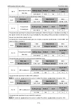
P2.42
Disturbance
observer
compensation gain
Setting range
Default
Unit
Applicable
mode
0–100
0
%
P
S
This parameter specifies the compensation gain for disturbance torque. Increasing the gain may
improve the effect of suppressing disturbance impact but the noise may increase. This parameter
needs to be used with P2.43 to find the best setting point. After setting P2.43, increase the setting
of P2.42.
P2.42
Data size
16bit
Data format
DEC
Modbus address
1484, 1485
CANopen address
0x222A, 0x00
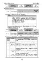
P2.43
Disturbance observer
cut-off frequency
Setting
range
Default
Unit
Applicable
mode
0–3000
200
Hz
P
S
This parameter specifies the cut-off frequency of the disturbance observer. Decreasing the setting
of this parameter may decrease noise, while increasing the setting may decrease the disturbance
torque compensation delay. This parameter needs to be used with P2.42.
P2.43
Data size
16bit
Data format
DEC
Modbus address
1486, 1487
CANopen address
0x222B, 0x00
P2.44
Torque command offset
Setting range Default
Unit
Applicable
mode
-500.0–500.0
0.0
%
P
S
T
This parameter specifies the changeable load compensation which is added to the torque
command. It is usually be used in the vertical shaft application scenario, which excludes the torque
control mode.
P2.44
Data size
16bit
Data format
DEC
Modbus address
1488, 1489
CANopen address
0x222C, 0x00
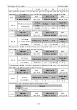
P2.50
2
Fully-closed loop vibration
suppressor
Setting range Default
Unit
Applicable
mode
0
–2
0
-
This parameter specifies whether the speed observer is valid.
Setting
Meaning
[
0
]
Invalid
1
Disturbance observation
2
Disturbance compensation
P2.50
2
Data size
16bit
Data format
DEC
Modbus address
1500, 1501
CANopen address
0x2232, 0x00


