ASI – The leader in Advanced Systems Integration | www.asimedical.net
TRiTOn
™
ADVAnceD DenTAl SySTeMS
®
2025M | 2025M/DV | 2025M/AR
44
65-2025M Rev. B
7.6 Adjusting Handpiece Pressure
Drive air pressures for handpieces are pre-set at the factory to the recommended
operating pressures for handpieces. To adjust the drive air pressure setting for
each handpiece, you will need to access the control block located underneath the
cover of the system. To gain access to the control block, please refer to Opening
Cover to Delivery System.
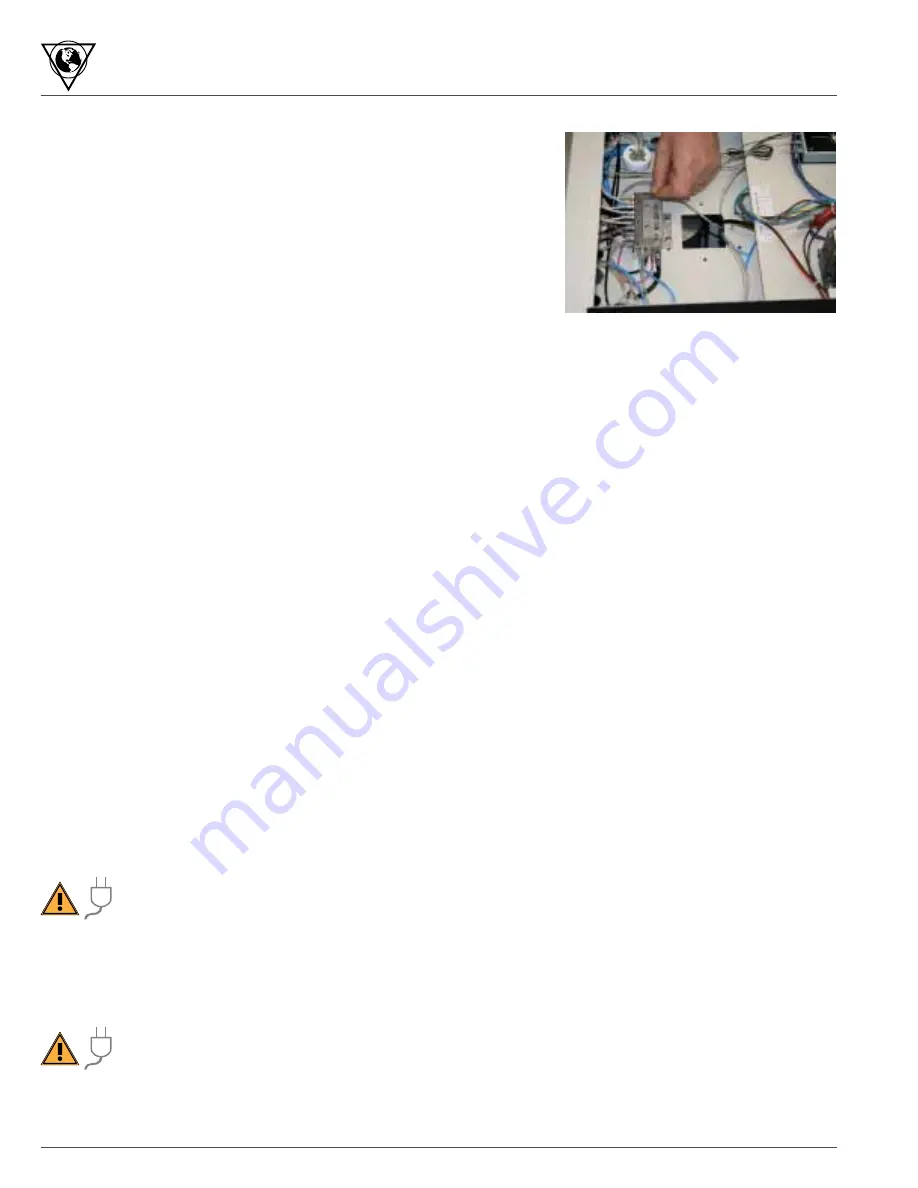
The adjustment controls for the control block are inside the delivery system in the
center of the bottom panel (see Figure 7.6–A).
The handpiece pressure adjustments are small set screws or knobs and will be
labeled with abbreviations for the type of instrument installed as follows:
FHS - Fiber Optic High Speed (air driven)
HS - High Speed (air driven)
EHLS - Electric High Low Speed
ELS - Electric Low Speed
LS - Low Speed (air driven)
US - Ultrasonic
Adjustment screws for electric instruments should be left in a fully open position to allow free air flow to pressurize and exhaust
off of the air/electric switches. Knobs are placed on adjustment screws to allow easier adjustment of operating air pressures for
air operated high and low speed handpieces.
To adjust the drive air pressure for each handpiece, perform the following steps:
1. Remove the handpiece from its holder. A handpiece must be connected to the tubing in order to register pressure on the
gauge.
2. Depress the foot control and read the handpiece pressure gauge on the front of the unit.
3. Rotate the handpiece air adjustment (clockwise to decrease, or counter-clockwise to increase pressure) until the desired
air pressure range is achieved, as specified by the handpiece manufacturer’s instructions.
7.7 Opening Back Panel
WARninG: electrical Shock – Unplug unit before opening service panel.
Access to the internal air compressor and air tanks, vacuum pump, canister and purge pump and cooling fan is
provided through the back panel. To gain access, use a medium sized flat blade screwdriver and turn the two
slotted cam latches on the left side of the door. Completely unwind the purge hose and the power cord. Then open the door.
7.8 Servicing or Replacement of Air compressor
instructions for Replacing the Air compressor and/or Manifold
WARninG: electrical Shock – Unplug unit before opening service panel.
Before starting, ensure that the power cord is unplugged to prevent accidental electrical shock!
To replace an entire air compressor assembly, follow the instructions below. To also service the manifold or install a rebuild kit,
it will be necessary to remove and replace the air compressor.
Figure 7.6–A


