ASI – The leader in Advanced Systems Integration | www.asimedical.net
TRiTOn
™
ADVAnceD DenTAl SySTeMS
®
2025M | 2025M/DV | 2025M/AR
53
65-2025M Rev. B
7.15.3 Replace Pressure Head
Tools Needed: Wire Cutters/Scissors, #2 Phillips head screwdriver
cAUTiOn: Pressurized Air Supply
1. Turn off air supply to unit.
2. Slowly unscrew bottles to relieve all air pressure in the bottles.
3. Remove existing bottles from bracket.
4. To gain access to the screws holding the pressure heads, it will be necessary to peel the label back from the top. It is
not necessary to completely remove. Just peel back far enough to gain access to the screws.
5. Remove screws to release the pressure head.
6. Grasp pressure head and clip off tubing right at the barb, noting the location of each tubing.
NOTE: The tubing on bottom barb is blue and the top is yellow.
7. Re-attach tubing to new pressure head barbs. Make sure the tubing is completely seated and sleeved
8. Place pressure head back up inside bracket and align the holes on top of pressure head with the holes in bracket with
the screws, then tighten the screws.
9. Press the label back onto the top of the bracket.
10. Fill bottles and attach. Turn system on to pressurize bottles. Test for leaks and proper water flow by running the Air/
Water syringe or Micro Irrigator handpiece.
7.16
compressed Air System
7.16.1 Remove/Replace Air compressor
Tools Needed: Wire Cutters, 10/32 Hex Head screwdriver, 7/16” Allen Wrench, Wire Crimper, #2 Phillips Head
cAUTiOn: Pressurized Air Supply
1. Unplug cart from main power.
2. Run Air syringe to relieve all compressed air in system.
3. Open Door located on the back of the cart to access the compressor and vacuum.
4. Locate Main Air tubing coming from compressor, it is a white semi-opaque tubing.
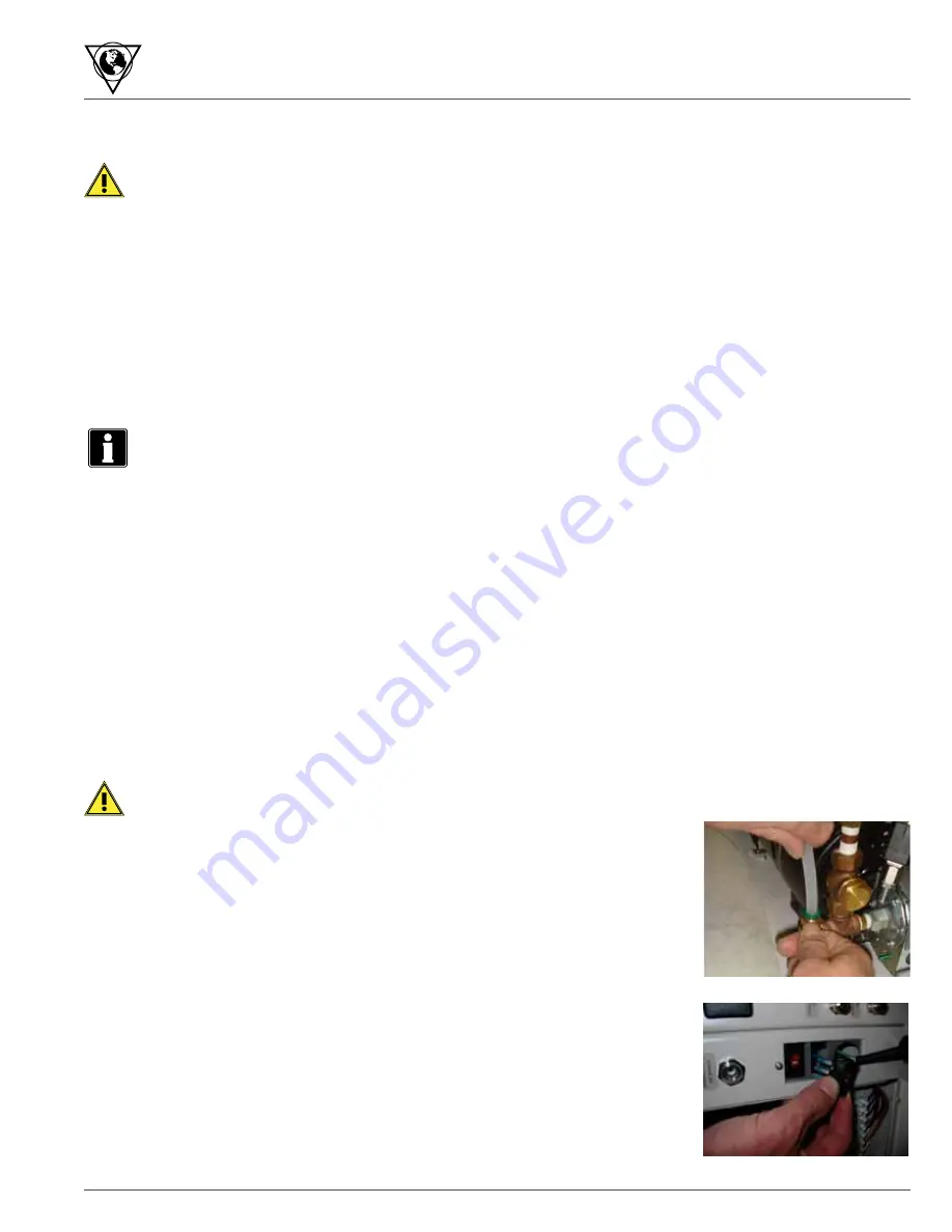
Disconnect white tubing from compressor by pressing down on green ring with one
thumb, push tubing down into connector then lift tubing out of connector. (Fig.1)
5. Locate wires coming from compressor and follow them to the voltage selection switch.
6. Press the bottom and top tabs on back of the switch and push out. Carefully remove
wires by pulling off slide connectors. (Fig.2)
Fig. 2
Fig. 1


