background image

54 


175.0020 - DECADE Elite service manual - rev 03 


4. Mounting additional sensor board 

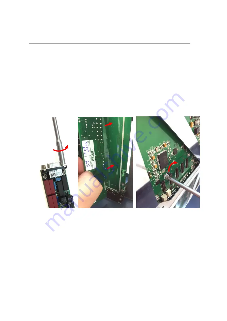
To mount an additional sensor board perform the following steps: 


Remove the two hex screws from the new sensor board supplied 
in the k

it using the 3/16” socket wrench. 


Place 

the new sensor board in the slot ‘Sensor 2’ (in case a SCC 

is upgraded to a DCC) by inserting the pin header on the sensor 
board into the corresponding socket on the control board.   


Fix the sensor board on the back side of the control board by 
means of the M3 x 8mm screw with a plastic washer supplied in 
the mounting kit using a Phillips PH-1 screw driver. 


Figure 11 Left: Remove hex screws from new sensor board. Middle: insert 
the second sensor board in socket designated ‘Sensor 2’. Right: fix sensor 
board on the back side of the control board with M3x8mm screw.  


Remove the plastic cover strip from the sensor board connector 
opening (sensor 2) on the EMC enclosure using a tweezer or other 
pointed metal object. Bend the metal retaining clips outwards to be 
able to shove them from the plastic fixing pins (see photo on next 
page). 


Re-install the metal EMC cover onto the sensor boards and fix it 
using the four M3x5mm screws. 


Fix the sensor board connectors from both board to the EMC en-
closure using the four 3/16” hex screws. 

Summary of Contents for DECADE Elite

Page 1: ...T 31 71 5813333 info AntecScientific com www AntecScientific com Antec Scientific Industrieweg 12 2382 NV Zoeterwoude The Netherlands DECADE Elite Service Manual 175 0020 Edition 3 2018...

Page 2: ...demarks of Antec Whatman word and device and Whatrnan word only are trademarks of Whatman lnternational Ltd SOLVENT IFD and AQUEOUS IFD are trademarks of Arbor Technologies Inc Clarity DataApex are tr...

Page 3: ......

Page 4: ...y generated and or used conductively coupled radio frequency energy which is necessary for the internal functioning of the equip ment itself Class A equipment is equipment suitable for use in all esta...

Page 5: ...egree as chemical laboratory technician or compara ble vocational training Fundamental knowledge of liquid chromatography Participation in an installation of the system performed by the man ufacturer...

Page 6: ...icted on the left site The symbol on the product indicates that the product must not be disposed as unsorted municipality waste Collection recycling information Please ship the instrument back to the...

Page 7: ...ons for service 21 Reset to factory defaults 21 Enter service mode 21 Chapter 4 DECADE Elite FW upgrade 23 Software installation 23 Upgrading firmware 25 STEP 1 Export DECADE Elite calibration setting...

Page 8: ...ving EMC enclosure 53 4 Mounting additional sensor board 54 5 Opening the cell cabinet 56 6 Installation of internal cell cable 58 7 Reconnecting wiring mounting rear panel 59 CHAPTER 7 61 Replacing t...

Page 9: ...ge or destruction of parts or all of the equipment Do not proceed beyond a warning sign until the indicated conditions are fully under stood and met The caution sign denotes a hazard It calls attentio...

Page 10: ...lite service manual rev 03 The attention sign signals relevant information Read this information The note sign signals additional information It provides advice or a suggestion that may support you in...

Page 11: ...he instrument is checked regularly and maintenance procedures are car ried out Preventive maintenance contracts are available for that Purpose Please contact your local dealer or the nearest sales off...

Page 12: ...may be flammable toxic or corrosive The room in which the system is installed should be well ventilated to prevent that sol vent vapors cause poisoning or ignite and cause a fire Use of open fire in...

Page 13: ...in the oven compartment Do not allow flammable and or toxic solvents to accumulate Follow a regulated approved waste Disposal program Never dispose of flammable and toxic solvents through the municipa...

Page 14: ...14 175 0020 DECADE Elite service manual rev 03...

Page 15: ...CADE Elite has 3 operational measurement modes DC SCAN and PULSE mode Furthermore a Service Diag nostics and Config ura tion mode are available In addition crucial parameters can be controlled by rela...

Page 16: ...rument description DECADE Elite Front side Description Description 1 Instrument housing 7 and value keys 2 LC tubing inlet outlet 8 Cursor keys 3 Instrument door panel 9 Door handle for opening door 4...

Page 17: ...ar panel 7 USB connector USB B 2 Type label pn sn etc 8 Fuse power rating 3 Digital I O connector 25 pins sub D fem 9 Mains switch inlet 4 Analog data 9 pins sub D fem 10 Grounding stud 5 Valve connec...

Page 18: ...inet 8 Column clamp 2 Cell connector 9 pins sub D fem 9 Mounting hole for cell clamp M4 3 Top fan heater intake 10 Bottom fan heater exhaust 4 Door sensor 11 Mounting hole for column clamp M3 5 Mounti...

Page 19: ...gure 1 Screwdriver socket wrench and Phillips PH 1 screwdriver from left to right Calibrated temperature sensor must have a tolerance at 45oC equal or better than 0 1oC Suggested model Extech RTD 4079...

Page 20: ...control and firmware updates To be able to run an OQ PQ and automated calibration scripts an Elite Dialogue USB license key pn 171 9012 is required Elite Dialogue is backward compatible old Dialogue...

Page 21: ...A message appears RESET TO FACTORY SETTINGS If yes factory settings will be loaded reset of operational parameters Ecell range filter temperature Enter service mode In main screen press enter for mor...

Page 22: ...22 175 0020 DECADE Elite service manual rev 03...

Page 23: ...installed in the directory C Program Files x86 Antec Elite Dialogue After installation a new application group named Antec will ap pear in the Windows Start Menu containing a link named Elite Di alogu...

Page 24: ...ith the detector connect the B plug of the cable into the USB port on the rear panel of the instrument Figure 2 Left rear panel DECADE Elite with USB cable connected B type connector Right rear panel...

Page 25: ...ch on the DECADE Elite detector and start the Elite Dialogue software on your PC The select devices menu will pop up Check the DECADE Elite and Connect Elite via USB check box and select the correspon...

Page 26: ...e during boot up Make sure that the Auto mode checkbox is NOT checked The upgrade procedure consists of 5 steps Export and store the existing DECADE Elite calibration settings to the Personal Computer...

Page 27: ...ion settings By clicking the Export calibration settings button the DECADE Elite cali bration settings will be saved to PC The following instruction screen will pop up The calibration data will be sav...

Page 28: ...should typically be 0 If all these values are 0 this is an indication that the sensor board was not calibrated or lost its calibration settings for some reason Always make a safety copy of the calibr...

Page 29: ...ctor and the Erase software will upload to the instrument automatically STEP 3 Formatting test DECADE Elite memory Subsequently the detector will reboot automatically and the erase software will start...

Page 30: ...o the instrument STEP 5 Import calibration settings The fifth and last step in the process is importing the previously stored cali bration settings from the PC into the DECADE Elite Start this step by...

Page 31: ...t tings will be send to the instrument after clicking OK Close Elite Dialogue Switch the detector off and on again Start the Elite Dialogue software and reconnect the instrument Goto Options menu Devi...

Page 32: ...ot up correctly and will show the error message In that case repeat the upload procedure as described in this chapter If the error persists please contact your supplier Be careful with the calibration...

Page 33: ...menus can be accessed which will be described in the next sections of this chapter SETT tings menu TEST menu ADJ ustments menu In the top right corner of the service mode main menu the active sensor b...

Page 34: ...ts SETT This enables the time file editor and the ability to run time files This functionality is unsupported in the DECADE Elite Use Elite Dialogue to run timed events C tslock SETT Limit maximum sam...

Page 35: ...52 O u t p u t s a r e I n a c t i v e P R E V A C T I N A C T M E M 53 S R A M m e m o r y t e s t P R E V S T A R T M E M 54 S R A M m e m o r y t e s t i n p r o g r e s s M E M 55 S R A M m e m o...

Page 36: ...e 3 I O connection set supplied with the DECADE Elite Measure the output status of all individual outputs using a calibrated volt meter A TTL outputs connect the minus of the voltmeter to common pin 2...

Page 37: ...is high 3 3V IN put test The input status of all individual input pins is reflected in the LCD display If a short circuit with common pin 25 is made the corresponding pin status will change to zero S...

Page 38: ...f TTL contact is high 3 3V Programmable Inputs see DECADE Elite user manual for details In case the output input test fails repeatedly please consult your Antec rep resentative MEM ory test With the m...

Page 39: ...0 0 6 8 n A Z E R I E 1 59 O f f s 1 0 R 1 M O h m A D C 1 8 8 2 5 3 0 C P R E V A U T O U N D O R E S E T I D 1 60 R e s e t c a l i b r a t i o n f o r a l l r a n g e s Y E S N O O U T P 1 61 O u...

Page 40: ...A 100M 0 2 pA Table V Parameters Parameter Screen Description Type R ZER IE Select active resistor of IE converter using or button Values are 100M 10M 1M 100k 1k Ohm C Ic ZER IE Residual current C ADC...

Page 41: ...to Output using the factory supplied output cable 2 Set Output Voltage to FULL 3 Adjust correction factor until measured Output voltage is within specs Using buttons 4 Check FULL and 0 0 V setting if...

Page 42: ...1 AUX 2 REF 3 2 Switch ON the flow cell 3 Press F3 and measure the 0 0 V value 4 Adjust offset correction NOT the gain correction until measured voltage is within specs 5 Press F2 and measure the 4 90...

Page 43: ...ing holes in the top left or top right side of the oven see white arrow 2 Set both the sensor calibration factor and heater calibration factor to 0 0 C at the start of the procedure Figure 5 Take out...

Page 44: ...e Sensor calibration factor and Heater calibration factors in the TEMP menu to the values calculated at point 5 and 6 8 Let the instrument stabilize for 30 minutes and read the temperature of the exte...

Page 45: ...oftware This procedure is de scribed in document 171 0025 PM for DECADE and ROXY Parts for PM Calibration The following parts for device calibration are available from Antec Part no Description 171 90...

Page 46: ...46 175 0020 DECADE Elite service manual rev 03...

Page 47: ...0208 DECADE Elite Lite cell cable 1 250 0102A SenCell clamp kit 1 Carefully unpack the kit and inspect it for completeness and for possible damage Contact your supplier in case of damage or if not al...

Page 48: ...iring and mounting rear panel 8 Check calibration This procedure may only be executed by skilled authorized service engineers trained and certified by Antec the Netherlands The re moval of protective...

Page 49: ...electronic parts loosen the four M3 Phillips screws as depicted in the figure below using a Phillips PH 1 screw driver The screws are encircled in red Figure 6 Removing the rear panel of the DECADE El...

Page 50: ...rtment with out any problem as depicted in the figure above 2 Disconnecting internal wiring Remove all cables connected to the control board below the blank metal EMC casing with white label as depict...

Page 51: ...Move the PCB frame a bit more backwards to make the internal cell cable connection to the sensor board accessible Remove the internal cell cable from the clamp located on the top side of the PCB fram...

Page 52: ...on on sensor board 1 Top middle remove internal cell ca ble from the cable clamp Top right loosen the 2 hex screws fixing the in ternal cell cable to the sensor board connector and disconnect the cabl...

Page 53: ...e EMC enclosure from the control board Figure 10 Left remove the hex screws fixing sensor board 1 and from sensor board 2 if present to the EMC enclosure Middle loosen the EMC enclosure by unscrewing...

Page 54: ...washer supplied in the mounting kit using a Phillips PH 1 screw driver Figure 11 Left Remove hex screws from new sensor board Middle insert the second sensor board in socket designated Sensor 2 Right...

Page 55: ...by bending the retaining clips outwards with a tweezer or pointed metal object and shove the complete metal plate of the plastic pin Figure 13 Control board with 2 sensor boards under the EMC enclosur...

Page 56: ...columns etc from the oven compartment Remove the 4 rubber liners of the inlet outlet tubing openings in the detector oven compartment position of the liners marked by a red arrow Remove the 4 M3 x 8mm...

Page 57: ...ide of the cell cabinet until the top side of the isolated heater compartment is obstructed by the top panel of the detector Do not put any tension on the electronic wiring connected to the cell cabin...

Page 58: ...nternal cell cable before installation The label should be applied on the thin unshielded black lead close to the male connector on the cable Fix the cell connector of the internal cell cable female c...

Page 59: ...top side of the PCB frame Reconnect all wiring power heater fans door sensor temp sen sor keyboard and LCD display connectors on the control board Insert the cables of the door sensor fans and tempera...

Page 60: ...if neces sary as described page 25 Let the instrument equilibrate with the oven set to 35 C for at least half an hour Check and calibrate the instrument as described in Chapter 4 ei ther via the SERVI...

Page 61: ...nt can result in exposure to potentially dangerous voltages Therefore always disconnect the instrument from all power sources before disassembly Removing the PSU frame To access the PSU remove the PSU...

Page 62: ...sonably sharp edges Do not put any tension on the electronic wiring connected to the PSU it may lead to damage and malfunction of the detector Figure 19 Top removal of 6 M3x8m screws encircled in red...

Page 63: ...e to access the screws fixing the wiring Remove the transparent plastic cover strip shielding the wiring connections Loosen the screws of the PSU connectors fixing the wires of the primary and seconda...

Page 64: ...iption L Brown Line N Blue Neutral Green yel low Protective ground V Black 0V V Black 0V V Orange 24V control board V Orange 24V heater Make sure that all wires are firmly connected again to the corre...

Page 65: ...oosen the three M4x6mm screws fixing the PSU on the PSU frame located on the side of the PSU using a Phillips PH 2 screw driver loosen the M3x5mm screws fixing the PSU on the PSU frame lo cated on the...

Page 66: ...he PSU frame Place the new PSU with the PSU fan outlet facing downwards on top of the corresponding ventilation holes in the PSU frame Do not install the PSU with the fan outlet facing upwards this mi...

Page 67: ...e detector Fix all 4 M3X8mm screws to secure the PSU frame Flip the detector back in its original position on the lab table standing on its instrument feet Reconnect the power cable into the mains inl...

Page 68: ...68 175 0020 DECADE Elite service manual rev 03...

Page 69: ...pright on flat smooth surface keep space under the detector free risk of blocking power supply fan Power requirements 110 240 VAC 50 60 Hz 260 VA auto sens ing Mains fuse 2 5 AT 250V 5x20 mm IEC 60127...

Page 70: ...J45 LAN 1x 9 pins sub D Male Valve 1x 9 pins sub D Female Analog output 1x 25 pins sub D Female Digital I O Analog output DAC 1 to 1 V full scale via 16 bit D A converter Analog output I E 2 5 to 2 5...

Page 71: ...2 50 V with 10 mV increments Data Rate 1 pulse duration Hz Waveform Max 5 potential steps Pulse times t1 t5 t1 100 ms 2000 ms t2 t3 t4 t5 0 2000 ms in 10 ms increments Sampling times ts 20 ms t1 60 ms...

Page 72: ...72 175 0020 DECADE Elite service manual rev 03...

Reviews: