background image

Configuring Communication

37

MVP-5200i Modero Viewpoint Widescreen Touch Panel

5.

In the new window:


Select 

Use the following IP Address

.


Under 

IP address

, provide an IP address (ensure that it is in the same subnet as the IP address 

given to the usb0 interface on the MVP-5200i).


Under 

Subnet mask

, set the suitable subnet mask.


Click on 

OK

'

6.

In the

 Local Area Connection 3 Properties

 window, click on 

OK

.

The user should now be able to run any TCP/IP application between the two systems.

Configure a Virtual NetLinx Master using NetLinx Studio

A Virtual NetLinx Master (VNM) is used when the target panel is not actually connected to a physical 
NetLinx Master. In this situation, the PC takes on the functions of a Master via a Virtual NetLinx Master. 
This connection is made by either using the PC’s Ethernet Address (via TCP/IP using a known PC’s IP 
Address as the Master) or using a direct mini-USB connection to communicate directly to the panel.

Before beginning:

1.

If using the mini-USB connection, verify the panel has been configured to communicate via USB 
within the 

System Settings

 page and that the USB driver has been properly configured. Changing the 

Master Connection type requires a reboot before the change takes effect.
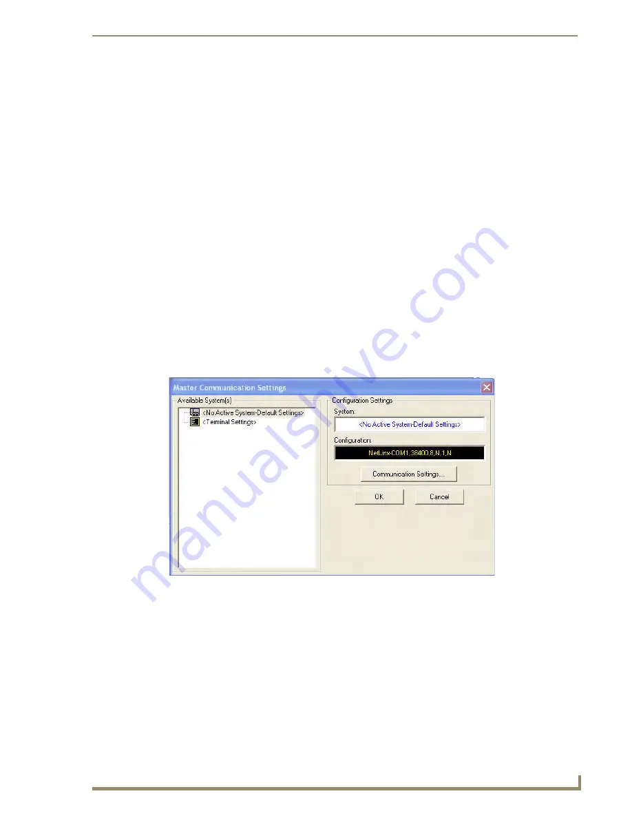
2.

In NetLinx Studio, select 

Settings

 > 

Master Communication Settings

, from the Main menu to 

open the 

Master Communication Settings

 dialog (FIG. 34). 

FIG. 34  

Master Communications Settings dialog box

Summary of Contents for Modero Viewpoint MVP-5200i

Page 1: ...Operation Reference Guide Mio Modero Touch Panels MVP 5200i Modero Viewpoint Widescreen Touch Panel Last Updated 4 23 2010 ...

Page 2: ... whichever is greater Products that are returned and exhibit signs of damage or unauthorized use will be processed under the Non Warranty Repair Policy AMX will continue to provide Warranty Repair Services for products discontinued or replaced by a Product Discontinuance Notice Non Warranty Repair Policy Products that do not qualify to be repaired under the Warranty Repair Policy due to age of the...

Page 3: ...tions However there is no guarantee that interference will not occur in a particular installation If this equipment does cause harmful interference to radio or television reception which can be determined by turning the equipment off and on the user is encouraged to try to correct the interference by one or more of the following measures Reorient or relocate the receiving antenna Increase the sepa...

Page 4: ...PLIED WARRANTIES OF MERCHANTABILITY AND FITNESS FOR A PARTICULAR PURPOSE WITH REGARD TO THE AMX SOFTWARE THIS LIM ITED WARRANTY GIVES LICENSEE SPECIFIC LEGAL RIGHTS Any supplements or updates to the AMX SOFTWARE including without limitation any if any service packs or hot fixes provided to Licensee after the expiration of the ninety 90 day Limited Warranty period are not covered by any warranty or...

Page 5: ... Touch Panel 13 Installing the panel on a NetLinx system 13 Establishing a wireless connection with AMX WAP 13 Configuring the device 13 Locating the device in NetLinx Studio 13 Verifying and upgrading the firmware 13 Downloading custom touch panel pages 13 Power Management 14 Wireless Interface Cards 15 802 11b Wireless Interface Card 15 Specifications 15 NXA WC80211GCF 802 11g Wireless Interface...

Page 6: ...card for secured access to a WAP200G 33 Automatically set SSID 34 Manually set SSID 34 Configuring multiple wireless Moderos to communicate to a target WAP200G 37 Step 3 Choose a Master Connection Mode 38 Ethernet over USB 38 Touch panel setup 39 Setting up a device IP address 41 Configure a Virtual NetLinx Master using NetLinx Studio 42 Ethernet 44 Master Connection to a Virtual Master via Ethern...

Page 7: ...1 EAP FAST Settings 84 EAP PEAP Settings 86 EAP TTLS Settings 88 EAP TLS Settings 90 Client certificate configuration 91 System Settings Page 93 EAP Security Server Certificates Overview 95 Programming 97 Overview 97 Navigation Wheel Programming 97 Page Commands 97 Programming Numbers 104 RGB triplets and names for basic 88 colors 104 Font styles and ID numbers 106 Border styles and Programming nu...

Page 8: ...0 Terminology 161 EAP Authentication 164 EAP characteristics 164 EAP communication overview 165 AMX Certificate Upload Utility 166 Configuring your MVP 5200i for USB Communication 166 Step 1 Setup the Panel and PC for USB Communication 166 Step 2 Confirm the Installation of the USB Driver on the PC 167 How to Upload a Certificate File 168 Appendix C Troubleshooting 169 Panel Doesn t Respond To Tou...

Page 9: ...et Protocol VoIP communication with all control established through a NetLinx Master Besides offering the same functionality as the rest of AMX s line of G4 touch panels the MVP 5200i touch panel offers full duplex VoIP communication quick wakeup and connection time and an extended battery life for longer operation between charges The MVP 5200i device utilizes a 5 2 Color Active LCD to display a 8...

Page 10: ... Power Requirements While Charging Panel while charging battery Constant current draw 1 1 A 12 VDC Startup current draw 1 3 A 12 VDC Minimum Power Supply Required PS3 0 Power Supply FG423 30 both 120 VAC and 240 VAC models are shipped with this power supply Power Modes AWAKE All necessary modules are powered up and device remains online with the Netlinx Master ASLEEP Only the backlight will be tur...

Page 11: ...r between the PC and the target panel Note When connecting the panel to PC using a CC USB or compatible cable be sure to power the panel On before attempting to connect the USB cable from the PC to the mini USB port on the panel DC power port 2 5 mm port to power the panel away from a Charging Station Stylus Slot Slot where the included stylus is stored located on the right side of the device Micr...

Page 12: ... Replacement Kit FG5966 27 MVP STYLUS 52 GB Black Replacement Stylus Pack of 3 FG5966 21 MVP STYLUS 52 GW White Replacement Stylus Pack of 3 FG5966 22 CC USB USB Programming Cable FG10 5965 MVP HP USB 1 8 Adapter FG5966 23 This device complies with FCC Part 15 and Industry Canada RSS 210 subject to the following conditions 1 This device must not cause harmful interference and 2 This device must ac...

Page 13: ...ng and adjusting by turning the wheel with a thumb or finger and then pressing down on one of the wheel s compass points for up down left and right The wheel is sensitive enough to adjust levels with one third of a rotation The center of the navigation wheel also acts as a button in its own right for example pressing down directly upon the wheel center may be used for the equivalent of an Enter ke...

Page 14: ... and whether the blink function for the LED while in sleep mode is enabled Navigation Wheel behavior in each Power Mode Power Mode Power Status Enters Mode By Exits Mode By LED Behavior Sleep Blink Setting Notes Enabled Disabled Awake Full On Battery Power N A N A ON ON Awake Full On External Power N A N A ON ON Awake Full On Charging N A N A BLINK BLINK Sleep Display Off Battery Power 1 Display T...

Page 15: ... storage groove on the right side of the device when not in use Replacement styluses may be ordered in a 3 pack FG5966 30 xx from www amx com Navigation Wheel behavior in each Power Mode Cont Power Mode Power Status Enters Mode By Exits Mode By LED Behavior Sleep Blink Setting Notes Enabled Disabled Stand By Display Off Electronics halted Battery Power Enabled Advanced Power Management 1 Display T...

Page 16: ...or more information see the Accessories section on page 9 for details When not in active use the MVP 5200i conserves battery life between chargings In its Sleep Mode the device s entire system is shut down with only wakeup systems powered to detect incoming commands or touch panel contact Pressing any of the compass points on the navigation wheel will return the device to its Active Mode For more ...

Page 17: ... that the device s base is in full contact with the table surface press the cord into the locking groove running across the bottom of the device 3 Provide power to the MVP TCS by connecting the PS3 0 cord to an external power source FIG 5 MVP TCS 52 GB Table Charging Station Front MVP TCS 52 Specifications Dimensions HWD 8 0 x 4 75 x 3 5 20 32cm x 12 07cm x 8 89cm Weight 65 lbs 29 kg Rear Connecto...

Page 18: ... 7 must be in contact with the connector on the bottom of the MVP 5200i for it to start recharging The MVP panel will stop recharging automatically once the battery has achieved its maximum charge Cleaning the MVP TCS 52 You should clean the Table Charging Station after each day s use to maintain the device s appearance Always use a clean cotton cloth and a spray bottle containing water or a vineg...

Page 19: ...rity Integrated docking alignment guides for easy docking Panel eject design with mechanical or electronically controlled capabilities FIG 8 MVP WCS 52 GB Wall Charging Station Front MVP WCS 52 Specifications Dimensions HWD 8 375 x 6 09 x 2 19 21 27 cm x 15 46 cm x 5 56 cm Note Always use the cutout installation dimensions for the MVP WCS 52 when installing this unit into various surfaces This SP ...

Page 20: ...panel and the MVP WCS 52 Support Cradle This retractable mechanism supports a resting MVP panel and allows a user to either insert or remove a connected MVP panel Security Release pushbutton Located on the front of the unit this pushbutton toggles an on screen security keypad if security is enabled Entering the correct release code allows the MVP WCS 52 to release the touch panel from the security...

Page 21: ...l the device s ejection door has completely withdrawn before re installing the MVP 5200i Recharging To recharge the MVP 5200i 1 Slide the device into the Wall Charging Station cradle bottom first and make sure the device is fully seated in the Charging Station 2 Press the top of the MVP 5200i back until it clicks The touch panel is now locked into the Charging Station and the station will automati...

Page 22: ...level of support To install the Plastic Back Box 1 Cut a hole into the wall or surface intended to hold the box The outer lip of the box is sized 8 69 inches 220 66mm long and 6 0 inches 152 4mm high so the hole should be at least 1 4 6 4mm smaller in each dimension FIG 10 Use the included MVP WCS 52 Wall Charging Station Template 68 5966 01 as an aid for hole placement and measurement 2 Select th...

Page 23: ...ures that the wing will tighten up against the inside of the wall 6 Prepare the captive wires for the 2 pin 3 55 mm mini captive wire connector used for the MVP WCS 52 s power supply To assist with wiring and to avoid mechanical stresses on the wire and the mechanism of the Wall Mounted Charging Station the top right knockout is preferred for use FIG 11 Installation of plastic back box Note Orient...

Page 24: ...ors included in the Installation Kit at the top rear of the device FIG 12 Point the head of each tie wrap toward the center of the device 8 Firmly seat the mini captive wire connector to the power connector on the device 9 Firmly seat the device against the box Make sure that the tab connector at the top of the device is locked into the box 10 Insert the two installation screws from the MVP WCS 52...

Page 25: ...nt bottom first Press the top of the touch panel until it is flush with the Wall Charging Station The neodymium magnets will hold it in place 13 To remove the MVP 5200i unlock the touch panel see the Unlocking the touch panel section on page 13 for more information and wait for the touch panel to pull away from the Wall Charging Station Once it has been released grip it by the top of the device an...

Page 26: ...he adjoining stud or spacer to secure it The interior of the box contains a set of holes on either side as well as top and bottom for standard 1 4 inch screws Use these holes to anchor the box to its adjoining studs or spacers The box has two sets of knockouts in the top and bottom one of the set for US wiring and one for international wiring After completing the installation of the metal rough in...

Page 27: ... device The box is sized 8 375 inches 21 27cm long and 5 75 inches 14 60cm high so the hole should be at least 1 4 0 64cm smaller in these dimensions To facilitate the full range of movement of the device s components the recess must be at least 2 69 inches 6 83cm deep Ensure that the power cable has been installed in the wall and is accessible by the installer before chiseling out the recess Inst...

Page 28: ...Accessories 20 MVP 5200i Modero Viewpoint Widescreen Touch Panel ...

Page 29: ...s As with any other WAP network the gateways are spaced so as to allow a maximum wireless coverage for the three devices When initially installing the MVP 5200i some basic configuration items including network settings and NetLinx settings will need to be set For more information refer to the Protected Setup Pages section on page 61 Before commencing verify you are using the latest NetLinx Master ...

Page 30: ...et 6 10 m from the panel at frequencies of 38KHz 455KHz and 1 2MHz IR receivers and transmitters on G4 panels share the device address number of the panel The MVP 5200i includes an IR transmitter for communication between the device and the NetLinx Master and between separate devices The transmitter is located behind the IR Emitter Panel on the rear of the device FIG 16 FIG 16 IR transmitter windo...

Page 31: ...gation wheel for 3 5 seconds This opens a release notice to release the button immediately to open the Setup page FIG 17 2 Press the Protected Setup button This opens a keypad for entry of the password to allow access to the Protected Setup page FIG 18 Enter the device s password and press Done to proceed For more information on the Setup and Protected Setup pages refer to the Setup Pages section ...

Page 32: ... communication parameters must match those of the pre installed wireless CF card inside the device MVP touch panels connect to a wireless network through their use of the pre installed AMX 802 11g wireless interface card This allows users to communicate with a Wireless Access Point WAP The WAP communication parameters must match those of the pre installed wireless interface card installed within t...

Page 33: ...om the MVP panel to the web Wireless communication using a DHCP Address In the Protected Setup page 1 Select Wireless Settings Wireless communication is set within the IP Settings section of this page FIG 19 2 Toggle the DHCP Static field from the IP Settings section until the choice cycles to DHCP This action causes all fields in the IP Settings section other than Host Name to be greyed out 3 Pre...

Page 34: ...lds 4 Press the optional Host Name field to open the keyboard and enter the Host Name information Press Done after assigning the alpha numeric string of the host name 5 Press the Primary DNS field to open a Keyboard enter the Primary DNS Address provided by the System Administrator and press Done when compete Repeat this process for the Secondary DNS field 6 Press the Domain field to open a Keyboa...

Page 35: ...he Site Survey button This action launches the Wireless Site Survey page which displays a listing of all detected WAPs in the communication range of the internal card The card scans its environment every four seconds and adds any new WAPs found to the list Every scan cycle updates the signal strength fields Access points are tracked by MAC Address If the WAP s SSID is set as a blank then N A is di...

Page 36: ...ding Settings page For any other security mode clicking Connect will only return to the previous page without any information being entered In an Open security mode after selection and connection to a target WAP the SSID name of the selected WAP is saved for the open security mode In a Static WEP security mode after selection and connection to a WEP Access Point the user is then redirected back to...

Page 37: ...ters for the target Master see Step 3 Choose a Master Connection Mode section on page 33 Configuring the device s wireless card for unsecured access to a WEP In the Protected Setup page 1 Press the Wireless Settings button located on the lower left to open the Wireless Settings page FIG 21 2 Enter the SSID information by Automatically filling it by pressing the Site Survey button From the Site Sur...

Page 38: ...omplete 7 From the Open Clear Text Settings page FIG 23 press the Save button to incorporate the new information into the device and begin the communication process 8 Verify the proper configuration in the fields in the IP Settings section Refer to Step 1 Configure the Device s Wireless IP Settings section on page 25 for detailed information 9 Press the Back button to return to the Protected Setup...

Page 39: ...ge and press the Connect button FIG 24 4 If the security is not handled automatically the information must be entered manually from the Wireless Security menu Manually setting SSID From the Protected Setup page 1 Select Wireless Settings 2 Locate the Wireless Security menu FIG 25 FIG 24 Site Survey of available WAPs Secured WAP shown selected FIG 25 Wireless Security page Select a target WAP with ...

Page 40: ...it level of encryption security This WEP encryption level must match the encryption level being used on the WAP 6 Toggle the Default Key field to choose a WEP Key value from 1 4 that matches what will be used on the target This value MUST MATCH on both devices These WEP Key identifier values must match for both devices 7 Verify that the fields within the IP Settings section have been properly conf...

Page 41: ...onnection to be made between it and the Master To establish a Master connection 1 From the Protected Setup page select System Settings 2 Select Type to toggle between the Master Connection Types USB and Ethernet FIG 27 A USB connection is a direct connection from the panel s mini USB port to a corresponding USB port on the PC acting as a Virtual Master A wireless Ethernet connection involves indir...

Page 42: ... and wait for the device to finish booting up 2 Insert the mini USB end of the USB Programming Cable into the mini USB port on the device Insert the other end into the appropriate USB port on the computer containing the files to be downloaded 3 If the connection goes well the Windows XP machine will detect the device as an unsupported USB device It then presents a dialogue box that prompts the use...

Page 43: ...t driver in these locations Select Include this location in the search Click on Browse Select the folder that contains the linux inf file 7 Click on Next 8 The Windows XP machine now searches for the suitable driver FIG 31 FIG 30 Found New Hardware Wizard Installation Options dialogue box FIG 31 Found New Hardware Wizard while searching for the driver ...

Page 44: ...et the Windows network properties for the Ethernet over USB interface to have a specific address whenever the Windows XP system detects an MVP 5200i with an assigned IP address In Windows XP 1 From the Windows XP desktop click on Start Settings Network Connections This opens a window listing the currently active network connections 2 Select the connection that is specific to AMX USB Device Link 3 ...

Page 45: ...ctually connected to a physical NetLinx Master In this situation the PC takes on the functions of a Master via a Virtual NetLinx Master This connection is made by either using the PC s Ethernet Address via TCP IP using a known PC s IP Address as the Master or using a direct mini USB connection to communicate directly to the panel Before beginning 1 If using the mini USB connection verify the panel...

Page 46: ...tab in the Workspace window to view the devices on the Virtual System 10 Right click on Empty Device Tree System and select Refresh System to re populate the list The panel will not appear as a device below the virtual system number in the Online Tree tab until both the system number default 1 is entered into the Master Connection section of the System Settings page and the panel is restarted The ...

Page 47: ...button to reboot the device and confirm changes Connection Modes Mode Description Procedures None No connection None Auto The device connects to the first master that responds This setting requires setting the System Number Setting the System Number 1 Select the System Number to open the keypad 2 Set your System Number and select Done URL The device connects to the specific IP of a Master via a TC...

Page 48: ... Settings dialog FIG 37 3 Click the Communications Settings button to open the Communications Settings dialog FIG 38 4 Click on the Virtual NetLinx Master radio button from the Platform Selection section to indicate that you are working as a NetLinx Master When configuring the panel to communicate with a Virtual Master on your PC via wireless Ethernet the Master IP URL field must be configured to ...

Page 49: ... Enter cmd into the Open field and click OK to open the command DOS prompt From the C command line enter ipconfig to display the IP Address of the PC This information is entered into the Master IP URL field on the panel 8 Click OK to close the open dialogs save the settings and return to the main NetLinx Studio application 9 Click the OnLine Tree tab in the Workspace window to view the devices on ...

Page 50: ...tware applications such as NetLinx Studio TPD4 or IREdit 16 Press the Master IP URL field to open a Keyboard and enter the IP Address of the PC used as the Virtual Master 17 Click Done to accept the new value and return to the System Settings page 18 Do not alter the Master Port Number value as this is the default value used by NetLinx 19 Press the Back button to open the Protected Setup page 20 P...

Page 51: ...nto the Keypad s password field 1988 is the default password with a new unit and press Done 4 Press the G4 WebControl button to open the G4 Web Control page FIG 41 5 Press the Enable Enabled button until it toggles to Enabled and turns light blue 6 The Network Interface Select field is read only and displays the method of communication to the web Wireless is used when a wireless card is detected w...

Page 52: ...3 Press the Web Control Port field to open the Web Port Number keypad 14 Within the keypad enter a unique numeric value to be assigned to the port on which the VNC Web Server is running The default value is 5900 Press Done after entering the value The remaining fields within the G4 Web Control Settings section of this page are read only and cannot be altered 15 Press the Up Down arrows on either s...

Page 53: ...urity page and no username and password is required for access or configuration Both HTTP and HTTPS Ports are enabled by default via the Manage System Server page If the Master has been previously configured for secured communication click OK to accept the AMX SSL certificate if SSL is enabled and then enter a valid username and password into the fields within the Login dialog 4 Click OK to enter ...

Page 54: ...d of communication is being used it can be found in either Wired Ethernet System Settings IP Settings section within the IP Address field Wireless Wireless Settings IP Settings section within the IP Address field If this field does not appear continue to step 9 8 If a WebControl password was set up on the G4 WebControl page a G4 Authentication Session password dialog box appears on the screen with...

Page 55: ...e panel 10 Click OK to send the password to the panel and begin the session A confirmation message appears stating Please wait Initial screen loading The secondary window is then populated with the same G4 page being displayed on the target G4 panel A small circle appears within the on screen G4 panel page and corresponds to the location of the mouse cursor A left mouse click on the computer displ...

Page 56: ...Configuring Communication 48 MVP 5200i Modero Viewpoint Widescreen Touch Panel ...

Page 57: ...to several essential panel properties Features on this page include FIG 46 Setup Page Access buttons FIG 47 MVP 5200i main Setup page Setup Page Navigation Buttons The buttons along on the left side of the page provide access to secondary Setup pages see following sections Connection Status icon The icon in the upper right corner of each Setup page provides a constant visual indication of current ...

Page 58: ...e navigation wheel center will NOT wake up the panel and only touching the touch screen will awaken it This feature is only active when the device is running on battery power and is not active when the device is on external power When enabled Advanced Power Savings allows additional battery life of panel availability without recharging This feature is not user settable in some firmware versions Di...

Page 59: ...ss to access the Protected Setup pages Press to access the Project Information page in order to view information on panel specific information such as resolution and memory Press to access the Time page in order to alter the time and date settings on the Master Press to access the Audio page in order to adjust audio parameters on the panel Press to access the Battery page in order to monitor batte...

Page 60: ...y loaded on the panel FIG 49 Features on this page include The Project Information and the Panel Information buttons will be displayed for three seconds before they slide back behind the Information button whether or not the Information button is still being pressed FIG 49 Project Information page Project Information Page Back Saves all changes and returns to the previous page Connection Status ic...

Page 61: ...panel IR User Def1 Port Displays the primary channel port used by the IR receiver on the panel IR User Def2 Port Displays the secondary channel port used by the IR receiver on the panel Build Number Displays the build number information of the TPD4 software used to create the project file Creation Date Displays the project creation date Revision Date Displays the last revision date for the project...

Page 62: ...el High Level Displays the high level level count value being used by the panel Serial Number Displays the specific serial number value assigned to the panel Setup Pages Version Displays the type and version of the Setup pages being used by the panel Screen Width Displays the screen width in pixels MVP 5200i 640 pixels Screen Height Displays the screen height in pixels MVP 5200i 480 pixels Screen ...

Page 63: ...con in the upper right corner of each Setup page provides a constant visual indication of current connection status Note a Lock appears on the icon if the panel is connected to a secured NetLinx Master Time Date Refresh Set The Get Time button retrieves Time and Date information from the Master The Set Time button retains and saves any time date modifications made on the panel Time Display fields ...

Page 64: ...left or right of the graph marker to adjust the volume level in one percent increments range 0 100 or press the bargraph and hold to move the graph marker to the desired level The Mute button toggles the Mute feature Default Panel Sounds Activating the Button Hit button plays a default sound when you touch an active button Activating the Button Miss button plays a default sound when you touch a no...

Page 65: ...ercom s microphone Use the Up Down buttons to adjust the microphone level range 0 100 Press the bargraph to the left or right of the graph marker to adjust the volume level in one percent increments range 0 100 or press the bargraph and hold to move the graph marker to the desired level Intercom Volume Sets the volume level for intercom calls from another MVP 5200i Use the Up Down buttons to adjus...

Page 66: ... the panel automatically shuts down Once shut down the device will have to be restarted The Up Down buttons alter the timeout value in minutes A value of 0 disables this feature Note Shutdown mode turns the unit completely off including communication circuits and preserves battery life unlike Display Timeout Sleep mode which only turns off display From Shutdown mode a unit must be turned on by pre...

Page 67: ...th two options Disable Clicking on this button deactivates this power save feature The panel will use the Panel Brightness level Disabled Clicking on this button activates the brightness limit set on the panel conserving battery power Activating this feature causes the panel to function at 80 of full brightness and overrides the Panel Brightness value set on the Setup page ...

Page 68: ...Setup Pages 60 MVP 5200i Modero Viewpoint Widescreen Touch Panel ...

Page 69: ...on the left side of the page provide access to secondary Protected Setup pages see following sections Back Saves all changes and returns to the previous page Connection Status icon The icon in the upper right corner of each Protected Setup page provides a constant visual indication of current connection status Note a Lock appears on the icon if the panel is connected to a secured NetLinx Master De...

Page 70: ... panel including the pre installed AMX Demo pages This option invokes a Confirmation dialog prompting you to confirm your selection before removing the panel pages Note that the YES button on the Confirmation dialog is disabled for 5 seconds as additional protection against accidentally resetting the panel or removing the panel pages Reboot Shutdown Panel Pressing the Reboot button causes the pane...

Page 71: ...cess the Passwords Setup page to specify firmware Press to access the Calibration page which allows proper calibration of the panel Press to access the Wireless Settings page which allows configuration of wireless Press to access the System Settings page which contains IP Settings and Master display and control of the panel via a web enabled PC running a VNC client and user access passwords connec...

Page 72: ...hat the IP address and the subnet mask fields are greyed out in Static press either of the fields to open the IP Address and Subnet Mask keypads Master Connection Sets the NetLinx Master communication values Type Sets the NetLinx Master to communicate with the panel via Ethernet USB Mesh or ICSNet This is based on the cable connection from the rear Ethernet is a CAT 5 cable 10 100Base T terminated...

Page 73: ...ster IP URL fields are read only URL UDP In this mode The System Number and Master IP URL fields are read only Auto In this mode enter the System Number and a username password if applicable Use this mode when both the panel and the NetLinx Master are on the same Subnet and the Master has its UDP feature enabled The Master IP URL field is read only System Number Allows entry of a system number Def...

Page 74: ...CP or Static communication modes DHCP a temporary IP Addresses is assigned to the panel by a DHCP server If DHCP is selected the other IP Settings fields are disabled see below Static IP is a permanent IP Address assigned to the panel If Static IP is selected the other IP Settings fields are enabled see below IP Address Enter the secondary IP address for this panel Subnet Mask Enter the subnetwork...

Page 75: ...k Name SSID entry of the target WAP so the panel knows what device it is using to communicate with the network Refer to the Open Clear Text Settings section on page 70 for further details Static WEP This button opens the Static WEP Settings page FIG 61 on page 71 Static WEP security requires that both a target WAP be identified and an encryption method be implemented prior to establishing communic...

Page 76: ...e 77 for further details RF Link Info These options set communication values for the wireless interface card SSID Displays the currently used SSID of the target WAP Channel The RF channel being used for connection to the WAP read only Link Quality Displays the quality of the link from the wireless NIC to the Wireless Access Point direct sequence spread spectrum in real time None Poor Fair Good Ver...

Page 77: ...o a target panel Refer to the Appendix B Wireless Technology section on page 180 for further information Some encryption and security features may or may not be supported Refer to the Configuring Wireless Network Access section on page 25 for more information on configuring the panel for wireless network access using the various security options Wireless Security Support 802 11g Wi Fi CF card Open...

Page 78: ...ty options FIG 60 Wireless Settings page Open Clear Text Settings Open Clear Text Settings SSID Service Set Identifier Opens an on screen keyboard to enter the SSID name used on the target WAP The SSID is a unique name used by the WAP and is assigned to all panels on that network An SSID is required by the WAP before the panel is permitted to join the network The SSID is case sensitive and must no...

Page 79: ...the panel is permitted to join the network The SSID is case sensitive and must not exceed 32 characters Make sure this setting is the same for all points in your wireless network NXA WAP200Gs use AMX as their default SSID If this field is left blank the panel will attempt to connect to the first available WAP WEP 64 WEP 128 Cycles through the available encryption options 64 or 128 Bit Key Size WEP...

Page 80: ...nd HEX keys are supported Up to four keys can be configured for both An ASCII key utilizes either 5 or 13 ASCII characters A HEX key utilizes either 10 or 26 Hexidecimal characters Press Done to accept any changes and save the new value Note A 64 bit key will be 10 characters in length while a 128 bit key will be 26 characters in length The length of the key entered determines the level of WEP enc...

Page 81: ...assword Pass Phrase Enter the SSID of the WAP Enter a pass phrase with a minimum of 8 characters and a maximum of 63 The exact same pass phrase including capitalization must be entered in the access point FIG 62 Wireless Settings page WPA PSK Settings WPA PSK Settings SSID Service Set Identifier Opens an on screen keyboard to enter the SSID name used on the target WAP The SSID is a unique name use...

Page 82: ...talled in a panel so that the RADIUS server can be validated before the panel tries to connect to it The field name associated with this file is Certificate Authority If a server certificate is used it should first be downloaded into the panel and the Certificate Authority field should then be set to the name of that certificate file No file path should be used for this setting as all certificates...

Page 83: ...n on screen keyboard is opened when these fields are selected LEAP Lightweight Extensible Authentication Protocol was developed to transmit authentication information securely in a wireless network environment EAP LEAP security is designed for wireless environments where having a client or server certificate validation scheme in place is not required yet necessary to transmit data securely over a ...

Page 84: ...cessful connection is not guaranteed because the detected WAP may be connected to a RADIUS server which may not support this EAP type and or have the proper user identities configured Identity Opens an on screen keyboard Enter an EAP Identity string used by the panel to identify itself to an Authentication RADIUS Server Note This information is similar to a username used to login to a secured serv...

Page 85: ... to all panels on that network An SSID is required by the WAP before the panel is permitted to join the network The SSID is case sensitive and must not exceed 32 characters Make sure this setting is the same for all points in the wireless network NXA WAP200Gs use AMX as their default SSID With EAP security the SSID of the WAP must be entered If it is left blank the panel will try to connect to the...

Page 86: ...cause the search for the PAC file is done automatically If Disabled is selected the user is required to manually locate a file containing the PAC shared secret credentials for use in authentication In this case the IT department must create a PAC file and then transfer it into the panel using the AMX Certificate Upload application Note Even when automatic provisioning is enabled the PAC certificat...

Page 87: ...over a wireless network environment PEAP uses only server side public key certificates and therefore does not need a client panel certificate which makes the configuration and setup easier There are two main versions of the PEAP protocol supported by panel s DeviceScape Wireless Client PEAPv0 PEAPv1 PEAP uses inner authentication mechanisms supported by the DeviceScape Wireless Client the most com...

Page 88: ...ich is similar to the password entered to gain access to a secured workstation Typically this is in the form of a username such as jdoe amx com Password Opens an on screen keyboard to enter the network password string specified for the user entered within the Identity field used by the panel to identify itself to an Authentication RADIUS Server Note This information is similar to the password ente...

Page 89: ...validation is done by tunneling a connection through the WAP and directly between the panel and the Radius server Once the client is identified and then validated the Radius server disconnects the tunnel and allows the panel to access the network directly via the target WAP FIG 68 Wireless Settings page EAP TTLS Settings EAP TTLS Settings SSID Service Set Identifier Opens an on screen keyboard to ...

Page 90: ...com Password Opens an on screen keyboard Enter the network password string specified for the user entered within the Identity field used by the panel to identify itself to an Authentication RADIUS Server Note This information is similar to the password entered to gain access to a secured workstation Certificate Authority When pressed the panel displays an on screen Certificate Authority CA File Lo...

Page 91: ...assigned to all panels on that network An SSID is required by the WAP before the panel is permitted to join the network The SSID is case sensitive and must not exceed 32 characters Make sure this setting is the same for all points in the wireless network NXA WAP200Gs use AMX as their default SSID With EAP security the SSID of the WAP must be entered If it is left blank the panel will try to connec...

Page 92: ... Certificate Opens an on screen keyboard for entering the name of the file containing the client panel certificate for use in certifying the identity of the client panel Refer to the Client certificate configuration section on page 85 for information regarding Client Certificates and their parameters Private Key When pressed the panel displays an on screen Client Private Key File Location keyboard...

Page 93: ...S and TLS The following table outlines the firmware fields and their supported certificate types Client Certificate Configuration Certificate Configuration Client Certificate Field Private Key Field Single file contains both the client certificate and the private key Format is PEM or DER Enter the file name Enter the same file name First file contains the client certificate second file contains th...

Page 94: ...54 2 Press the crosshairs in turn If the crosshairs are not touched within ten seconds the MVP 5200i will return to the Protected Setup page 3 The page will read Calibration Successful Touch to continue Touch anywhere on the screen to return to the Protected Setup page Always calibrate the panel before its initial use and after downloading new firmware FIG 70 Calibration page If the screen is not ...

Page 95: ...ed activates G4 Web Control on the panel Network Interface Select Toggles between the two network interface options Wireless the panel is communicating via a Wireless Access Point WAP Wired the panel is communicating via its mini USB port Web Control Name Use this field to enter a unique alpha numeric string to be used as the panel s display name within the Manage WebControl Connections window of ...

Page 96: ...VP 5200i Modero Viewpoint Widescreen Touch Panel Refer to the Using G4 Web Control to Interact with a G4 Panel section on page 43 for instructions on using the G4 Web Control page with the web based NetLinx Security application ...

Page 97: ...er than using a RAM cache Note that since static images are already stored on Flash they are never moved to the Flash cache so Flash caching applies only to dynamic images Images in Flash cache are moved back to RAM cache the next time they are viewed As the Flash cache approaches its maximum size the least recently used items may be discarded to make room for new items FIG 72 Cache Settings Page ...

Page 98: ...was referenced since the last cache clearing Items In Cache RAM The total number of cached images in the RAM cache Flash Current Size The maximum size allocated to the flash cache Flash Hit Rate The number of times the flash cache was referenced since the last cache clearing Items in Cache Flash The total number of cached images in the flash cache ...

Page 99: ...ted to the selected password group Note Clearing Password 5 removes the need to enter a password before accessing the Protected Setup page User Access Use these buttons to access and modify the user name password combinations required for removing the panel from a docking station The number of user access passwords on the panel is limited only by the amount of storage memory available Use the UP D...

Page 100: ...rd enter the user s password and press Done 3 Press the password button in the right column of the User Access section 4 Enter the new password into the Password keyboard and press Done To view all previous instances of users accessing the device 1 From the Password Settings page press the Enable button to highlight it The MVP 5200i will record all successful and unsuccessful attempts to access th...

Page 101: ...device protocol It parses the buffer for responses from the device sends strings to control the device and receives commands from the UI module or telnet sessions Refer to the documentation supplied with the Duet Module for more details Features on this page include A sample UI module is provided in the module package It is not intended to cover every possible application but can be expanded as ne...

Page 102: ... server that you want to use to register Port Number The option displays the port you use to connect to the proxy server The standard SIP port is 5060 but some providers use different ports STUN Address This option enables you to enter the IP address or DNS name of the Simple Traversal of UDP through NATs STUN server This field is optional Local Domain This is the realm used for authentication Thi...

Page 103: ...e Tools button menu will remain visible for three seconds regardless of whether or not the button continues to be held FIG 76 Panel Connection Logs Page Panel Connection Logs Page Back Saves all changes and returns to the previous page Connection Status icon The icon in the upper right corner of each Protected Setup page provides a constant visual indication of current connection status Note a Loc...

Page 104: ...vides a constant visual indication of current connection status Note a Lock appears on the icon if the panel is connected to a secured NetLinx Master ICSP Messages Lists the number of ICSP messages received processed and dropped both in total and within the last 15 minutes Blink Messages Lists the number of blink messages received and missed both in total and within the last 15 minutes Ethernet St...

Page 105: ... Information WAP MAC The WAP s MAC address SSID Displays the currently used SSID of the target WAP Channel The channel being used for the current connection Link Quality Displays the current quality of the target WAP link Signal Strength Displays the current strength of the target WAP signal Connection Status icon The icon in the upper right corner of each Protected Setup page provides a constant ...

Page 106: ...Protected Setup Pages 98 MVP 5200i Modero Viewpoint Widescreen Touch Panel ...

Page 107: ...gher Instruction Manual for more information on how to download firmware to a touch panel The MVP 5200i uses a native RNDIS USB driver for USB over Ethernet communication When the device is connected to the downloading computer see instructions below for more details it creates a new LAN connection and the user will need to supply a static IP address for this to be enabled To enter a static IP add...

Page 108: ...section on page 186 2 Click the Communications Settings button to open the Communications Settings dialog box FIG 80 3 Click on the NetLinx Master radio button from the Platform Selection section 4 Click on the Virtual Master radio box from the Transport Connection Option section to configure the PC to communicate directly with a panel Everything else such as the Authentication is greyed out becau...

Page 109: ... the connection to the device The Connection Status Icon on the device may take up to five seconds to register the connection Step 3 Confirm and Upgrade the firmware via the USB port Use the CC USB Type A to Mini B 5 wire programming cable to provide communication between the mini USB Program port on the touch panel and the PC This method of communication is used to transfer firmware Kit files and...

Page 110: ...ech Center Firmware Files Modero Panels section of the website 6 Click on the desired Kit file link and after accepting the Licensing Agreement verify download of the Modero Kit file to a known location FIG 82 NetLinx Workspace window showing panel connection via a Virtual NetLinx Master Showing the Virtual Master firmware version and device number Shows Netlinx Studio version number Shows the cur...

Page 111: ... is greyed out 11 Click the Reboot Device checkbox if it is not already checked This causes the touch panel to reboot after the firmware update process is complete 12 Click Send to begin the transfer The file transfer progress is indicated on the bottom right of the dialog 13 After the file transfer is complete the panel will automatically reboot As the panel is rebooting temporarily unplug the US...

Page 112: ...ome cases network administrators will notice the NIC connection and reconfigure any PC that has connected to the MVP 5200i Business college and government installations are the type of installations that would be most affected and most home installations would not be affected To prevent the NIC connection from becoming the primary connection 1 From the Windows Start menu select Settings Control Pa...

Page 113: ...dow FIG 86 4 Under the Adapters And Bindings tab the user needs to make sure the Local Area Connection is not at the top of the Connections list If it is at the top of the list FIG 86 select it and use the down arrow to the right of the list to move it to the bottom of the list FIG 87 FIG 86 Advanced Settings window FIG 87 Moving the Local Area Connection ...

Page 114: ...lower Bindings for Local Area Connection field unselect ALL bindings by clicking on the checkboxes by each binding to remove the checks from each box FIG 88 6 When finished click OK to close the Advanced Settings window and save all changes FIG 88 Bindings for Local area list detail ...

Page 115: ...ed A one third rotation of this wheel causes a level change Navigation Wheel Specific Commands This command is used in NetLinx Studio and is case insensitive Verify you are using the latest NetLinx Master and Modero firmware as well as the latest version of NetLinx Studio and TPD4 Navigation Wheel Specific Commands WLD LED NUM ACTION Brightness Set the Sleep Blink LED behavior LED NUM indicates th...

Page 116: ...specified popup group Syntax CPG popup group name Variable popup group name 1 50 ASCII characters Name of the popup group Example SEND_COMMAND Panel CPG Group1 Clears all popup pages from the popup group Group1 DPG Delete a specific popup page from specified popup group if it exists Syntax DPG popup page name popup group name Variable popup page name 1 50 ASCII characters Name of the popup page po...

Page 117: ...coordinate y coordinate Variable popup page name 1 50 ASCII characters Name of the page the popup is displayed On Example SEND_COMMAND Panel PHP Popup1 75 0 Sets the Popup1 hide effect x coordinate value to 75 and the y coordinate value to 0 PHT Set the hide effect time for the specified popup page Syntax PHT popup page name hide effect time Variable popup page name 1 50 ASCII characters Name of t...

Page 118: ...d see example 2 Toggling refers to the activating deactivating On Off of a popup page This command works in the same way as the Toggle Popup command in TPDesign4 Syntax PPG popup page name page name Variable popup page name 1 50 ASCII characters Name of the popup page page name 1 50 ASCII characters Name of the page the popup is displayed On Example SEND_COMMAND Panel PPG Popup1 Main Toggles the p...

Page 119: ...sed see example 2 If the popup page is already on do not re draw it This command works in the same way as the Show Popup command in TPDesign4 Syntax PPN popup page name page name Variable popup page name 1 50 ASCII characters Name of the popup page page name 1 50 ASCII characters Name of the page the popup is displayed On Example SEND_COMMAND Panel PPN Popup1 Main Activates Popup1 on the Main page...

Page 120: ...name x coordinate y coordinate Variable popup page name 1 50 ASCII characters Name of the page the popup is displayed On Example SEND_COMMAND Panel PSP Popup1 100 0 Sets the Popup1 show effect x coordinate value to 100 and the y coordinate value to 0 PST Set the show effect time for the specified popup page Syntax PST popup page name show effect time Variable popup page name 1 50 ASCII characters ...

Page 121: ...page This command works in the same way as the Toggle Popup command in TPDesign4 Syntax PPOG popup page name page name Variable popup page name 1 50 ASCII characters Name of the popup page page name 1 50 ASCII characters Name of the page the popup is displayed On Example SEND_COMMAND Panel PPOG Popup1 Main Toggles the popup page Popup1 on the Main page from one state to another On Off Example 2 SE...

Page 122: ...m Red 159 0 0 04 Dark Red 127 0 0 05 Very Dark Red 95 0 0 06 Very Light Orange 255 128 0 07 Light Orange 223 112 0 08 Orange 191 96 0 09 Medium Orange 159 80 0 10 Dark Orange 127 64 0 11 Very Dark Orange 95 48 0 12 Very Light Yellow 255 255 0 13 Light Yellow 223 223 0 14 Yellow 191 191 0 15 Medium Yellow 159 159 0 16 Dark Yellow 127 127 0 17 Very Dark Yellow 95 95 0 18 Very Light Lime 128 255 0 19...

Page 123: ...Medium Blue 0 0 159 52 Dark Blue 0 0 127 53 Very Dark Blue 0 0 95 54 Very Light Purple 128 0 255 55 Light Purple 112 0 223 56 Purple 96 0 191 57 Medium Purple 80 0 159 58 Dark Purple 64 0 127 59 Very Dark Purple 48 0 95 60 Very Light Magenta 255 0 255 61 Light Magenta 223 0 223 62 Magenta 191 0 191 63 Medium Magenta 159 0 159 64 Dark Magenta 127 0 127 65 Very Dark Magenta 95 0 95 66 Very Light Pin...

Page 124: ...68 68 86 Grey14 17 17 17 87 Black 0 0 0 255 TRANSPARENT 99 53 99 Default Font Styles and ID Numbers Font ID Font type Size Font ID Font type Size 1 Courier New 9 19 Arial 9 2 Courier New 12 20 Arial 10 3 Courier New 18 21 Arial 12 4 Courier New 26 22 Arial 14 5 Courier New 32 23 Arial 16 6 Courier New 18 24 Arial 18 7 Courier New 26 25 Arial 20 8 Courier New 34 26 Arial 24 9 AMX Bold 14 27 Arial 3...

Page 125: ...ctive S 8 Double line 40 41 Diamond 55 9 Quad line TPD4 Border Styles by Name No Border styles No Border styles 1 None 27 Cursor Bottom 2 AMX Elite L 28 Cursor Bottom with Hole 3 AMX Elite M 29 Cursor Top 4 AMX Elite S 30 Cursor Top with Hole 5 Bevel L 31 Cursor Left 6 Bevel M 32 Cursor Left with Hole 7 Bevel S 33 Cursor Right 8 Circle 15 34 Cursor Right with Hole 9 Circle 25 35 Custom Frame 10 Ci...

Page 126: ... 195 74 Oval V 100x200 118 Menu Right Rounded 15 75 Picture Frame 119 Menu Right Rounded 25 76 Quad Line 120 Menu Right Rounded 35 77 Single Line 121 Menu Right Rounded 45 78 Windows Style Popup 122 Menu Right Rounded 55 79 Windows Style Popup Status Bar 123 Menu Right Rounded 65 80 Menu Bottom Rounded 15 124 Menu Right Rounded 75 81 Menu Bottom Rounded 25 125 Menu Right Rounded 85 82 Menu Bottom ...

Page 127: ...149 Menu Left Rounded 135 142 Menu Left Rounded 65 150 Menu Left Rounded 145 143 Menu Left Rounded 75 151 Menu Left Rounded 155 144 Menu Left Rounded 85 152 Menu Left Rounded 165 145 Menu Left Rounded 95 153 Menu Left Rounded 175 146 Menu Left Rounded 105 154 Menu Left Rounded 185 147 Menu Left Rounded 115 155 Menu Left Rounded 195 148 Menu Left Rounded 125 ...

Page 128: ...e In 1 10 second intervals Example SEND_COMMAND Panel ANI 500 1 25 100 Runs a button animation at text range 500 from state 1 to state 25 for 10 second APF Add page flip action to a button if it does not already exist Syntax APF vt addr range page flip action page name Variable variable text address range 1 4000 page flip action Stan dardPage Flip to standard page Prev iousPage Flip to previous pa...

Page 129: ...r all 88 Basic Colors table on page 114 for more information Example SEND_COMMAND Panel BCB 500 504 510 1 12 Sets the Off state border color to 12 Yellow Colors can be set by Color Numbers Color name R G B alpha colors RRGGBBAA and R G B colors values RRGGBB Refer to the RGB Values for all 88 Basic Colors table on page 114 BCF Set the fill color to the specified color Only if the specified fill co...

Page 130: ... order Determines what order each layer of the button is drawn Syntax BDO vt addr range button states range 1 5 1 5 1 5 1 5 1 5 Variable variable text address range 1 4000 button states range 1 256 for multi state buttons 0 All states for General buttons 1 Off state and 2 On state layer assignments Fill Layer 1 Image Layer 2 Icon Layer 3 Text Layer 4 Border Layer 5 Note The layer assignments are f...

Page 131: ...ired BLN Set the number of lines removed equally from the top and bottom of a composite video signal The maximum number of lines to remove is 240 A value of 0 will display the incoming video signal unaffected This command is used to scale non 4x3 video images into non 4x3 video buttons Syntax BLN vt addr range button states range number of lines Variable variable text address range 1 4000 button s...

Page 132: ...1 100 source address 1 4000 source state 1 256 codes BM Picture Bitmap BR Border CB Border Color CF Fill Color CT Text Color EC Text effect color EF Text effect FT Font IC Icon JB Bitmap alignment JI Icon alignment JT Text alignment LN Lines of video removed OP Opacity SO Button Sound TX Text VI Video slot ID WW Word wrap on off Example SEND_COMMAND Panel BMC 425 1 1 500 1 BR or SEND_COMMAND Panel...

Page 133: ...ont Styles and ID Numbers table on page 116 MI mask image Set the mask image Refer to the BMI command on page 127 for more information R Sets button location and also resizes the button Takes four parameters left top right bottom T text Set the text using ASCII characters empty is clear P bitmap Set the picture bitmap filename empty is clear I icon 01 9900 0 clear Set the icon using values of 01 9...

Page 134: ...rag increment Refer to the GDI command on page 133 for more information VI video ON OFF Set the Video either ON value 1 or OFF value 0 OT feedback type Set the Feedback Output Type to one of the following None Channel Invert ON Always ON Momentary or Blink SM Submit a text for text area button SF 1 or 0 Set the focus for text area button OP 0 255 Set the button opacity to either Invisible value 0 ...

Page 135: ...a Text area input masking button Syntax BML vt addr range max length Variable variable text address range 1 4000 max length 2000 0 no max length Example SEND_COMMAND Panel BML 500 20 Sets the maximum length of the text area input button to 20 characters BMP Assign a picture to those buttons with a defined address range Syntax BMP vt addr range button states range name of bitmap picture Variable va...

Page 136: ...BOP Set the button opacity The button opacity can be specified as a decimal between 0 255 where zero 0 is invisible and 255 is opaque or as a HEX code as used in the color commands by preceding the HEX code with the sign In this case 00 becomes invisible and FF becomes opaque If the opacity is set to zero 0 this does not make the button inactive only invisible Syntax BOP vt addr range button state...

Page 137: ...buttons with the variable text range of 500 504 510 515 The border style is available through the TPDesign4 border style drop down list Refer to theTPD4 Border Styles by Name table on page 117 for more information BOS Set the button to display either a Video or Non Video window Syntax BOS vt addr range button states range video state Variable variable text address range 1 4000 button states range ...

Page 138: ...range to set focus to multiple buttons Only one variable text address can be in focus at a time Syntax BSF vt addr range selection value Variable variable text address range 1 4000 selection value Unselect 0 and select 1 Example SEND_COMMAND Panel BSF 500 1 Sets the focus to the text area of the button BSM Submit text for text area buttons This command causes the text areas to send their text as s...

Page 139: ...specified address Syntax BVP vt addr range network password Variable variable text address range 1 4000 network password 1 50 ASCII characters Example SEND_COMMAND Panel BVP 500 PCLOCK Sets the password to PCLOCK for the specific PC control button BVT Set the computer control network port for the specified address Syntax BVT vt addr range network port Variable variable text address range 1 4000 ne...

Page 140: ...ss range 1 4000 actions Stan dardPage Flip to standard page Prev iousPage Flip to previous page Show Popup Show Popup page Hide Popup Hide Popup page Togg lePopup Toggle popup state ClearG roup Clear popup page group from all pages ClearP age Clear all popup pages from a page with the specified page name ClearA ll Clear all popup pages from all pages page name 1 50 ASCII characters Example SEND CO...

Page 141: ...in TPD4 through the Main menu Panel Generate Programmer s Report Text Only Format Readme txt Button Commands Cont GDI Change the bargraph drag increment Syntax GDI vt addr range bargraph drag increment Variable variable text address range 1 4000 bargraph drag increment The default drag increment is 256 Example SEND_COMMAND Panel GDI 7 128 Sets the bargraph with variable text 7 to a drag increment ...

Page 142: ...ph ramp down time Variable variable text address range 1 4000 bargraph ramp down time In 1 10th of a second intervals Example SEND_COMMAND Panel GRD 500 200 Changes the bargraph ramp down time to 20 seconds GRU Change the bargraph ramp up time in 1 10th of a second Syntax GRU vt addr range bargraph ramp up time Variable variable text address range 1 4000 bargraph ramp up time In 1 10th of a second...

Page 143: ... icon for On and Off states for buttons with variable text ranges of 500 504 510 515 IRM Set the IR channel Pulse the given IR channel for onTime in tenths of seconds Delay offTime in tenths of a second before the next IR pulse is allowed IRM allows the command itself to specify the port number IRM is needed because commands programmed on the panel itself can only be sent to a single port number c...

Page 144: ...nment to upper left corner for those buttons with variable text ranges of 500 504 510 515 JSI Set icon alignment using a numeric keypad layout for those buttons with a defined address range The alignment of 0 is followed by left top The left and top coordinates are relative to the upper left corner of the button Syntax JSI vt addr range button states range new icon alignment Variable variable text...

Page 145: ...mple SEND_COMMAND Panel JST 500 504 510 515 1 2 1 Sets the text alignment to the upper left corner for those buttons with variable text ranges of 500 504 510 515 MBT Set the Mouse Button mode On for the virtual PC Syntax MBT pass data Variable pass data 0 None 1 Left 2 Right 3 Middle Example SEND COMMAND Panel MBT 1 Sets the mouse button mode to Left Mouse Click MDC Turn On the Mouse double click ...

Page 146: ...by name and can be found in TPD4 Syntax TEF vt addr range button states range text effect name Variable variable text address range 1 4000 button states range 1 256 for multi state buttons 0 All states for General buttons 1 Off state and 2 On state text effect name Refer to the Text Effects table on page 140 for a listing of text effect names Example SEND_COMMAND Panel TEF 500 504 510 515 1 2 Soft...

Page 147: ... send the variable text A in unicode to all states of the variable text button 1 for which the character code is 0041 Hex send the following command SEND_COMMAND TP UNI 1 0 0041 Note Unicode is always represented in a HEX value TPD4 generates through the Text Enter Box dialog unicode HEX values Refer to the TPDesign4 Instruction Manual for more information MVP Strings to Master undock master This ...

Page 148: ...e 2 SEND_COMMAND Panel LPS Manager test Changes the given user name password to test Refer to the Other Settings section on page 89 for more information Text Effects Glow S Medium Drop Shadow 1 Hard Drop Shadow 1 Glow M Medium Drop Shadow 2 Hard Drop Shadow 2 Glow L Medium Drop Shadow 3 Hard Drop Shadow 3 Glow X Medium Drop Shadow 4 Hard Drop Shadow 4 Outline S Medium Drop Shadow 5 Hard Drop Shado...

Page 149: ...t Name CUSTOM_EVENT TP 529 1009 Text Effect Color CUSTOM_EVENT TP 529 1010 Word Wrap CUSTOM_EVENT TP 529 1011 ON state Border Color CUSTOM_EVENT TP 529 1012 ON state Fill Color CUSTOM_EVENT TP 529 1013 ON state Text Color CUSTOM_EVENT TP 529 1014 Border Name CUSTOM_EVENT TP 529 1015 Opacity Send_String 0 ButtonGet Id ITOA CUSTOM ID Type ITOA CUSTOM TYPE Send_String 0 Flag ITOA CUSTOM FLAG Send_Str...

Page 150: ...e text from the button text length string encode button text length Button Query Commands BCB Get the current border color Syntax BCB vt addr range button states range Variable variable text address range 1 4000 button states range 1 256 for multi state buttons 0 All states for General buttons 1 Off state and 2 On state custom event type 1011 Flag zero Value1 Button state number Value2 Actual leng...

Page 151: ...ill color information The result sent to the Master would be ButtonGet Id 529 Type 1012 Flag 0 VALUE1 1 VALUE2 9 VALUE3 0 TEXT FF8000FF TEXT LENGTH 9 BCT Get the current text color Syntax BCT vt addr range button states range Variable variable text address range 1 4000 button states range 1 256 for multi state buttons 0 All states for General buttons 1 Off state and 2 On state custom event type 10...

Page 152: ...Panel BMP 529 1 Gets the button OFF state bitmap information The result sent to the Master would be ButtonGet Id 529 Type 1002 Flag 0 VALUE1 1 VALUE2 9 VALUE3 0 TEXT Buggs png TEXT LENGTH 9 BOP Get the overall button opacity Syntax BOP vt addr range button states range Variable variable text address range 1 4000 button states range 1 256 for multi state buttons 0 All states for General buttons 1 O...

Page 153: ...tate border information The result sent to the Master would be ButtonGet Id 529 Type 1014 Flag 0 VALUE1 1 VALUE2 22 VALUE3 0 TEXT Double Bevel Raised L TEXT LENGTH 22 BWW Get the current word wrap flag status Syntax BWW vt addr range button states range Variable variable text address range 1 4000 button states range 1 256 for multi state buttons 0 All states for General buttons 1 Off state and 2 O...

Page 154: ... font type index information The result sent to the Master would be ButtonGet Id 529 Type 1007 Flag 0 VALUE1 1 VALUE2 72 VALUE3 0 TEXT TEXT LENGTH 0 ICO Get the current icon index Syntax ICO vt addr range button states range Variable variable text address range 1 4000 button states range 1 256 for multi state buttons 0 All states for General buttons 1 Off state and 2 On state custom event type 100...

Page 155: ...tmap justification information The result sent to the Master would be ButtonGet Id 529 Type 1005 Flag 0 VALUE1 1 VALUE2 5 VALUE3 0 TEXT TEXT LENGTH 0 JSI Get the current icon justification Syntax JSI vt addr range button states range Variable variable text address range 1 4000 button states range 1 256 for multi state buttons 0 All states for General buttons 1 Off state and 2 On state custom event...

Page 156: ...t to the Master would be ButtonGet Id 529 Type 1004 Flag 0 VALUE1 1 VALUE2 1 VALUE3 0 TEXT TEXT LENGTH 0 TEC Get the current text effect color Syntax TEC vt addr range button states range Variable variable text address range 1 4000 button states range 1 256 for multi state buttons 0 All states for General buttons 1 Off state and 2 On state custom event type 1009 Flag Zero Value1 Button state numbe...

Page 157: ...be ButtonGet Id 529 Type 1008 Flag 0 VALUE1 1 VALUE2 18 VALUE3 0 TEXT Hard Drop Shadow 3 TEXT LENGTH 18 TXT Get the current text information Syntax TXT vt addr range button states range optional index Variable variable text address range 1 4000 button states range 1 256 for multi state buttons 0 All states for General buttons 1 Off state and 2 On state optional index This is used if a string was t...

Page 158: ...ters Example SEND COMMAND Panel AKB Texas Enter State Pops up the Keyboard and initializes the text string Texas with prompt text Enter State AKEYB Pop up the keyboard icon and initialize the text string to that specified Keyboard string is set to null on power up and is stored until power is lost Syntax AKEYB initial text Variables initial text 1 50 ASCII characters Example SEND COMMAND Panel AKE...

Page 159: ...th prompt text ENTER PASSWORD AKR Remove the Keyboard Keypad Remove keyboard or keypad that was displayed using AKEYB AKEYP PKEYP AKB AKP PKP EKP or TKP commands Syntax AKR Example SEND COMMAND Panel AKR Removes the Keyboard Keypad BEEP Output a beep Syntax BEEP Example SEND COMMAND Panel BEEP Outputs a beep BRIT Set the panel brightness Syntax BRIT brightness level Variable brightness level 0 100...

Page 160: ...ND Panel PKEYP 123456789 Pops up the Keypad and initializes the text string 123456789 in PKP Present a private keypad Pops up the keypad icon and initializes the text string to that specified Keypad displays a instead of the numbers typed The Prompt Text is optional Syntax PKP initial text prompt text Variables initial text 1 50 ASCII characters prompt text 1 50 ASCII characters Example SEND COMMA...

Page 161: ...2 1211 Enter Phone Number Pops up the Keypad and initializes the text string 999 222 1211 with prompt text Enter Phone Number TPAGEON Turn On page tracking This command turns On page tracking whereby when the page or popups change a string is sent to the Master This string may be captured with a CREATE_BUFFER command for one panel and sent directly to another panel Syntax TPAGEON Example SEND COMM...

Page 162: ...tring mechanism This process sends a virtual keystroke command VKS to the Master Example 2 SEND COMMAND Panel KPS 0 Disables the keyboard passthru to the Master The following point defines how the parameters within this command work Accepts keystrokes from any of these sources attached USB keyboard or Virtual keyboard VKS Send one or more virtual key strokes to the G4 application Key presses and k...

Page 163: ...ft key down 131 83 F1 132 84 F2 133 85 F3 134 86 F4 135 87 F5 136 88 F6 137 89 F7 138 8A F8 139 8B F9 140 8C F10 141 8D F11 142 8E F12 143 8F Num Lock 144 90 Caps Lock 145 91 Insert 146 92 Delete 147 93 Home 148 94 End 149 95 Page Up 150 96 Page Down 151 97 Scroll Lock 152 98 Pause 153 99 Break 154 9A Print Screen 155 9B SYSRQ 156 9C Tab 157 9D Windows 158 9E Menu 159 9F Up Arrow 160 A0 Down Arrow...

Page 164: ...sword level 1 4 page flip password 1 50 ASCII characters Example SEND COMMAND Panel PWD 1 Main Sets the page flip password on Password Level 1 to Main Dynamic Image Commands BBR Set the bitmap of a button to use a particular resource Syntax BBR vt addr range button states range resource name Variable variable text address range 1 4000 button states range 1 256 for multi state buttons 0 All states ...

Page 165: ... information Example SEND_COMMAND Panel RMF Sports_Image ALab_Test Images Ftest jpg Changes the resource Sports_Image file name to test jpg and the path to Lab_Test Images RSR Change the refresh rate for a given resource Syntax RSR resource name refresh rate Variable resource name 1 50 ASCII characters refresh rate Measured in seconds Example SEND_COMMAND Panel RSR Sports_Image 5 Sets the refresh ...

Page 166: ...een refreshes in which the resourceis downloadedagain Refreshinga resourcecauses thebutton displaying that resource to refresh also Thedefault value is 0 only download the resourceonce Full path to thelocation of thefile or program that will return the resource Thepath must bea valid HTTP URL minus theprotocol andhost The only exceptiontothis is the inclusion of special escapesequences and in thec...

Page 167: ...ND_COMMAND DEV ICS IP TX UDP port RX UDP port initial mode Variables IP IP Address of panel to connect with on an Intercom call TX UDP port UDP port to transmit to RX UDP port UDP port to receive from initial mode 0 listen or 1 talk or 2 handsfree 0 is the default Examples Example of setting up a handsfree unicast call between two panels send_command TP1 ICS 192 168 0 3 9000 9002 2 send_command TP...

Page 168: ...ample SEND_COMMAND TP1 ICM TALK ICM MICLEVEL Intercom modify command Used to set the microphone level during an intercom call Syntax SEND_COMMAND DEV ICM MICLEVEL Variables Valid levels are from 0 to 100 Example SEND_COMMAND TP1 ICM MICLEVEL 40 ICM MUTEMIC Intercom modify command Set the state of the microphone on a panel to muted 1 or unmuted 0 At the start of each call the microphone starts out ...

Page 169: ...ion Provides incoming call notification and the connection id used for all future commands related to this call The connection id will be 0 or 1 Syntax PHN INCOMING caller number caller name connection id timestamp Variable caller number The phone number of the incoming call caller name The name associated with the caller number connection id The identifying number of the connection timestamp The ...

Page 170: ...ges marked urgent Example SEND_COMMAND Panel PHN MSGWAITING 1 1 2 1 0 PHN PRIVACY Indicates the state of the privacy feature Syntax PHN PRIVACY state Variable state 0 Disable or 1 Enable new message count The number of new messages old message count The number of old messages new urgent message count The number of new messages marked urgent old urgent message count The number of old messages marke...

Page 171: ...PHN AUTOANSWER Queries the state of the auto answer feature The panel responds with the PHN AUTOANSWER state message Syntax PHN AUTOANSWER Example SEND_COMMAND Panel PHN AUTOANSWER PHN CALL Calls the provided number Syntax PHN CALL number Variable number The provided phone number Example SEND_COMMAND Panel PHN CALL 2125551000 PHN DTMF Sends DTMF codes Syntax PHN DTMF DTMF code Variable DTMF code 0...

Page 172: ...Queries the state of the privacy feature The panel responds with the PHN PRIVACY state message Syntax PHN PRIVACY Example SEND_COMMAND Panel PHN PRIVACY PHN REDIAL Redials the last number Syntax PHN REDIAL Example SEND_COMMAND Panel PHN REDIAL PHN TRANSFER Transfers the call to the provided number Syntax PHN TRANSFER connection id number Variable connection id The identifying number of the connect...

Page 173: ...N SETUP PORT 5060 PHN SETUP PROXYADDR Sets the IP address for the proxy server Syntax PHN SETUP PROXYADDR IP Variable IP The IP address for the proxy server Example SEND_COMMAND Panel PHN SETUP PROXYADDR 192 168 223 111 PHN SETUP STUNADDR Sets the IP address for the STUN server Syntax PHN SETUP STUNADDR IP Variable IP The IP address for the STUN server Example SEND_COMMAND Panel PHN SETUP STUNADDR...

Page 174: ...Programming 166 MVP 5200i Modero Viewpoint Widescreen Touch Panel ...

Page 175: ...ntact your AMX sales representative This installation requires opening the case of the MVP 5200i and working within its internal components If you are unwilling or unable to replace the battery please return the device to AMX for battery replacement WARNING Misuse of a Lithium Polymer battery may result in overheating fire or explosion To Avoid Injury Never Use near open flame or other heat source...

Page 176: ...e Awake mode Shutdown The system enters this mode after a user selectable amount of inactivity time has elapsed or if the battery level falls below10 percent of its full charge This is the absolute lowest mode of operation during which power to all peripherals and components is turned off It is not online with the NetLinx Master and will not appear in NetLinx Studio The system remains in this mode...

Page 177: ...nance To insure maximum performance and reliability of your AMX Wireless Touch Panel please insure that a full charge is performed every 3 months if not used regularly If a battery is left uncharged beyond this time frame it may result in premature battery lifespan degradation and will require replacement ...

Page 178: ...ontact AMX for replacement and proper disposal information 2 Place the device face down on a surface that will not scratch the unit and remove the five screws from the back of the device FIG 89 Two of the screws are at the upper corners of the device underneath rubber feet that also act as screw covers Remove the rubber feet to access the screws Lift up the kickstand and remove the label to reach ...

Page 179: ...ederal regulations If the battery comes in a protective metal case remove the two screws holding the battery case to the back cover Carefully remove the battery from the back cover Please dispose of the battery in a proper fashion as required by municipal or federal regulations Install the new battery Open the plastic bag containing the MVP BP 5X kit taking care not to use sharp instruments near t...

Page 180: ...e sure that the battery is not crimped or damaged upon closure of the case 2 Make sure to seat fully the battery plug to the connector in the device FIG 90 If fingers cannot be used use a clean nonconductive stick or probe to seat the connectors 3 Reattach the back of the device engaging the hook on the lower left of the case near the speaker and using it to swing the back down into place FIG 91 P...

Page 181: ... correctly 6 Attach the residual voltage discharge adaptor SAA5966 27 A to the old battery and allow any remaining charge to dissipate Note that the adaptor may become warm to the touch for up to 12 hours FIG 92 MVP 5200i back plate installation Rubber feet Upper screws Bottom label Bottom screw holes Front of MVP 5200i Back plate Bottom screws Speaker The three bottom screws are shorter than the ...

Page 182: ...Battery Life and Replacement 174 MVP 5200i Modero Viewpoint Widescreen Touch Panel ...

Page 183: ...he table below Bargraph Text Code Inputs Code Bargraph Multi State Bargraph P Display the current percentage of the bargraph derived from the Adjusted Level Value as it falls between the Range Values Display the current percentage of the bargraph derived from the Adjusted Level Value as it falls between the Range Values V Raw Level Value Raw Level Value L Range Low Value Range Low Value H Range Hi...

Page 184: ...ers i e numbers vs characters Limit the number of characters in a text area Suggest proper format with fixed characters Right to Left Required or Optional Change Force a Case Create multiple logical fields Specify range of characters number for each field Limit the user to a choice of selections Handle complex input tasks such as names days of the week or month by name Perform complex validation s...

Page 185: ...rs change the behavior of the field in the following way Input mask literals To define a literal character enter any character other than those shown in the above table including spaces and symbols A back slash causes the character that follows it to be displayed as the literal character For example A is displayed just as the letter A To define one of the following characters as a literal characte...

Page 186: ...lows from a numerical field the overflow value is added to the previous field on the chain if the overflow character was specified In the above example if the overflow flag was set the first example will place the 1 into the previous logical field and the second example will place 12 in the previous logical field If the overflow field already contains a value the new value will be inserted to the ...

Page 187: ...d For example the default port for http is 80 An alternative port could be specified as http www amx com 8080 company info home asp Special escape sequences The system has only a limited knowledge of URL formats as it transparently passes the URL information onto the server for translation A user can then pass any parameters to the server side programs such as CGI scripts or active server pages Ho...

Page 188: ...ways takes priority Example Imagine a panel connected to the two networks A B A is the wired network and B is the wireless network If the Master controller is on either of these networks then it will be reached However if the Master controller is on a different network C then the gateway determines which network interface wired or wireless will be used Wireless Access Points WAPs are the cornersto...

Page 189: ...ation authority The certificate authority CA is a trusted external third party which signs or validates the certificate When a certificate has been signed it gains some cryptographic properties AMX supports the following security certificates within three different formats PEM Privacy Enhanced Mail DER Distinguished Encoding Rules PKCS12 Public Key Cryptography Standard 12 Typical certificate info...

Page 190: ...Protected Access WPA and WPA2 is a class of system used to secure wireless Wi Fi computer networks It was created in response to several serious weaknesses researchers had found in the previous WEP system WPA implements the majority of the IEEE 802 11i standard and was intended as an intermediate measure to take the place of WEP while 802 11i was prepared WPA2 WPA is designed to work with all wire...

Page 191: ...tiality integrity and origin authentication WPA2 implements the full standard but will not work with some older network cards Both provide good security with two significant issues either WPA or WPA2 must be enabled and chosen in preference to WEP WEP is usually presented as the first security choice in most installation instructions in the Personal mode the most likely choice for homes and small ...

Page 192: ...oday are Microsoft Sever 2003 Juniper Odyssey once called Funk Odyssey Meetinghouse AEGIS Server DeviceScape RADIUS Server Cisco Secure ACS EAP characteristics The following table outlines the differences among the various EAP Methods from most secure at the top of the list to the least secure at the bottom of the list EAP Method Characteristics Method Credential Type Authentication Pros Cons EAP ...

Page 193: ... sends a EAP Response Identity message through the WAP to the RADIUS server providing its identity and specifying which EAP type it wants to use If the server does not support the EAP type then it sends a failure message back to the WAP which will then disconnect the panel As an example EAP FAST is only supported by the Cisco server 5 If the EAP type is supported the server then sends a message ba...

Page 194: ...r into the Mini USB Port on the panel It may take a minute for the panel to detect the new connection and send a signal to the PC indicated by a green System Connection icon If a few minutes have gone by and the System Connection icon still does not turn green complete the procedures in the following section to set up the Virtual Master and refresh the System from the Online Tree This action sends...

Page 195: ...guished Encoding Rules PEM Privacy Enhanced Mail PFX Normal Windows generated certificate PVK Private Key file How to Upload a Certificate File 1 Install the latest AMX USB LAN LINK driver onto your computer by installing the latest versions of either TPDesign4 or NetLinx Studio2 This USB driver prepares your computer for proper communication with the MVP 5200i Refer to Step 1 from within the Laun...

Page 196: ...ick the Add button to complete the entry and add the new IP Address to the listing of available device IP Addresses Repeat this process for all subsequent device IP Addresses 11 Once the list is complete click on the File drop down menu and select the Save option This launches a Save dialog to assign a name to the current list of addresses and then save the information as a TXT text file to a know...

Page 197: ...e on specific crosshairs when the sheet is pressing on the whole LCD The previous calibration may be off Reset the device calibration as explained in the Calibration Page section on page 86 Battery Will Not Hold Or Take A Charge Symptom The battery will not hold or take a charge and shows no indication of charging either on the bargraphs or in the Battery Setup page To keep the battery from being ...

Page 198: ...e IP Address field is still empty give the device a few minutes to negotiate a DHCP Address and try again My WEP Doesn t Seem To Be Working WEP will not work unless the same default key is set on both the panel and the Wireless Access Point WAP For example if the access point was set to default WEP key 4 which was 01 02 03 04 05 the Modero s Default WEP key 4 must be set to 01 02 03 04 05 NetLinx ...

Page 199: ...to each panel 1 Press and hold the two lower buttons on both sides of the display for 3 seconds to open the Setup page 2 Press the Protected Setup button located on the lower left of the panel page enter 1988 into the on screen Keypad s password field and press Done when finished 3 Enter a Device Number value for the panel into the Device Number Keypad The default is 10001 and the range is from 1 ...

Page 200: ...Appendix C Troubleshooting 192 MVP 5200i Modero Viewpoint Widescreen Touch Panel 4 Do your regular file or firmware download ...

Page 201: ...Appendix 193 MVP 5200i Modero Viewpoint Widescreen Touch Panel ...

Page 202: ... registered trademarks of AMX AMX reserves the right to alter specifications without notice at any time It s Your World Take Control 3000 RESEARCH DRIVE RICHARDSON TX 75082 USA 800 222 0193 469 624 8000 469 624 7153 fax 800 932 6993 technical support www amx com ...

Reviews: