


Overview
2
Enova DVX-3150HD/3155HD All-in-One Presentation Switcher Operation/Reference Guide
DVX-3150HD/DVX-3155HD Specifications
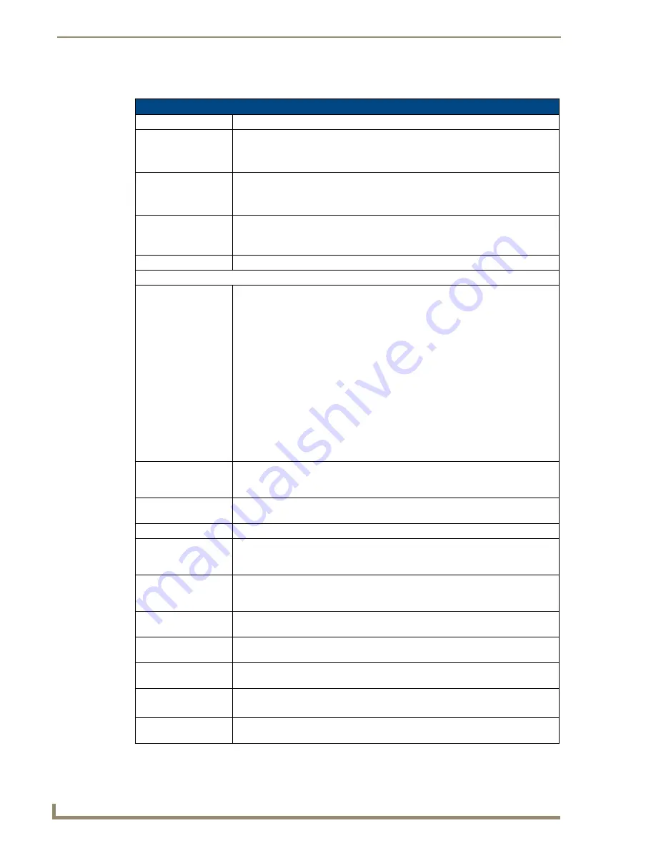
DVX-3150HD/DVX-3155HD Specifications
Power:
100-240V, 47/63 Hz AC supply
Power Consumption:
• 90 Watts typical without amplifier
• 95 to 100 Watts typical average with amplifier
• 30 Watts typical in low-power mode
Memory:
• 256 MB SDRAM
• 1 MB Non-volatile RAM (NVRAM)
• 256 MB Flash
Amplifier:
• 2 x 25W into 8 Ohms Class D stereo amplifier (capable of driving loads in the range
of 2-8 ohms) (-SP models only)
• 70V or 100V at 75W amplified variable mono audio (-T models only)
Integrated Controller:
Equivalent of a NetLinx 3101-SIG central controller on-board.
Front Panel Components:
LEDs:
• LINK/ACT (green) - Link/Activity LED lights when the Ethernet cables are
connected and terminated correctly and blinks when receiving Ethernet data
packets.
• STATUS (green) - Status LED blinks to indicate that the system is programmed and
communicating properly.
• INPUT (yellow) - Input LED blinks to indicate that the Controller is receiving data.
• OUTPUT (red) - Output LED blinks to indicate that the Controller is transmitting
data.
• RS-232/422/485 (red/yellow) - 6 sets of LEDs indicate that RS-232/422/485 Ports
(1-6) are transmitting or receiving data.
• RELAYS (red) - 8 LEDs indicate relay channels 1-8 are active (closed) on Port 8.
• IR/SERIAL (red) - 8 LEDs indicate that IR/Serial channels 1-8 are transmitting
control data on Ports 9-16.
• I/O (yellow) - 8 LEDs indicate that I/O channels 1-8 are active on Port 17.
LCD display:
Liquid crystal display (2 lines with 20 characters per line) indicates current volume
level and displays the Video, Audio, and Status menus. See the
LCD Display
section
on page 11 for details.
SWITCH
pushbutton:
Press to access the Switch menu on the LCD display. Use the menu to choose to
switch audio, video or both from any input to any output.
TAKE pushbutton:
While in the Switch menu, press to implement an audio/video switch.
VIDEO MENU
pushbutton:
Press to access the Video menu on the LCD display. There are two video menus
(VIDEO OUTPUT and VIDEO INPUT) and both are accessible by using this button.
Multiple presses cycle through the various VIDEO menus.
AUDIO MENU
pushbutton:
Press to access the Audio menu on the LCD display. There are three audio menus
(AUDIO OUTPUT, AUDIO INPUT, and MIC) and all are accessible by using this
button. Multiple presses cycle through the various AUDIO menus.
Navigational
pushbuttons:
4 directional buttons for navigating the options in the Switch, Video, Audio, and
Status menus (on the LCD display).
STATUS
pushbutton:
Press to access the STATUS menu on the LCD display on which you can view
system status and other system information.
EXIT pushbutton:
Press to exit the current menu and return to the default menu page, Main Amp
Output/Volume.
VIDEO MUTE
pushbutton:
Press to mute/un-mute (enable/disable) all video output displays.
Video Mute results in a blank screen on the output displays.
AUDIO MUTE
pushbutton:
Press to mute/un-mute all audio outputs.


