Cleaning, maintenance and repair
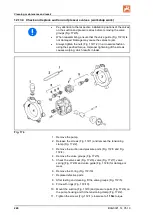
12.13.4 Check and replace suction and pressure valves (workshop work)
•
Pay attention to the respective installation positions of the valves
on the suction and pressure sides before removing the valve
groups (Fig. 172/5).
•
When reassembling, ensure that the valve guide (Fig. 172/9) is
not damaged. Damage may cause the valves to jam.
•
Always tighten the nuts (Fig. 172/1,2) in a crosswise fashion
using the specified torque. Improper tightening of the screws
causes warping, which results in leaks.
Fig. 174
1. Remove the pump.
2. Release the screws (Fig. 172/1) and remove the tensioning
clamp (Fig. 172/2).
3. Remove the suction and pressure ports (Fig. 172/3 and Fig.
172/4).
4. Remove the valve groups (Fig. 172/5).
5. Check the valve seat (Fig. 172/6), valve (Fig. 172/7), valve
spring (Fig. 172/8) and valve guide (Fig. 172/9) for damage or
wear.
6. Remove the O-ring (Fig. 172/10).
7. Replace defective parts.
8. After testing and cleaning, fit the valve groups (Fig. 172/5).
9. Fit new O-rings (Fig. 172/10).
10. Mount the suction (Fig. 172/3) and pressure ports (Fig. 172/4) on
the pump housing and fit the tensioning clamp (Fig. 172/2).
11. Tighten the screws (Fig. 172/1) crosswise to
11 Nm
torque
224
BAG0021.14 05.19
Summary of Contents for UG 2200 Special
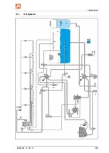
Page 237: ...Liquid circuit 13 1 UG Special BAG0021 14 05 19 237 ...
Page 238: ...Liquid circuit 13 2 UG Super 238 BAG0021 14 05 19 ...
Page 242: ...Spray table Fig 182 242 BAG0021 14 05 19 ...
Page 251: ...Spray table BAG0021 14 05 19 251 ...
Page 252: ......


