


6.3.11.8 Adjusting the press rollers
1
2
3
CMS-I-00001953
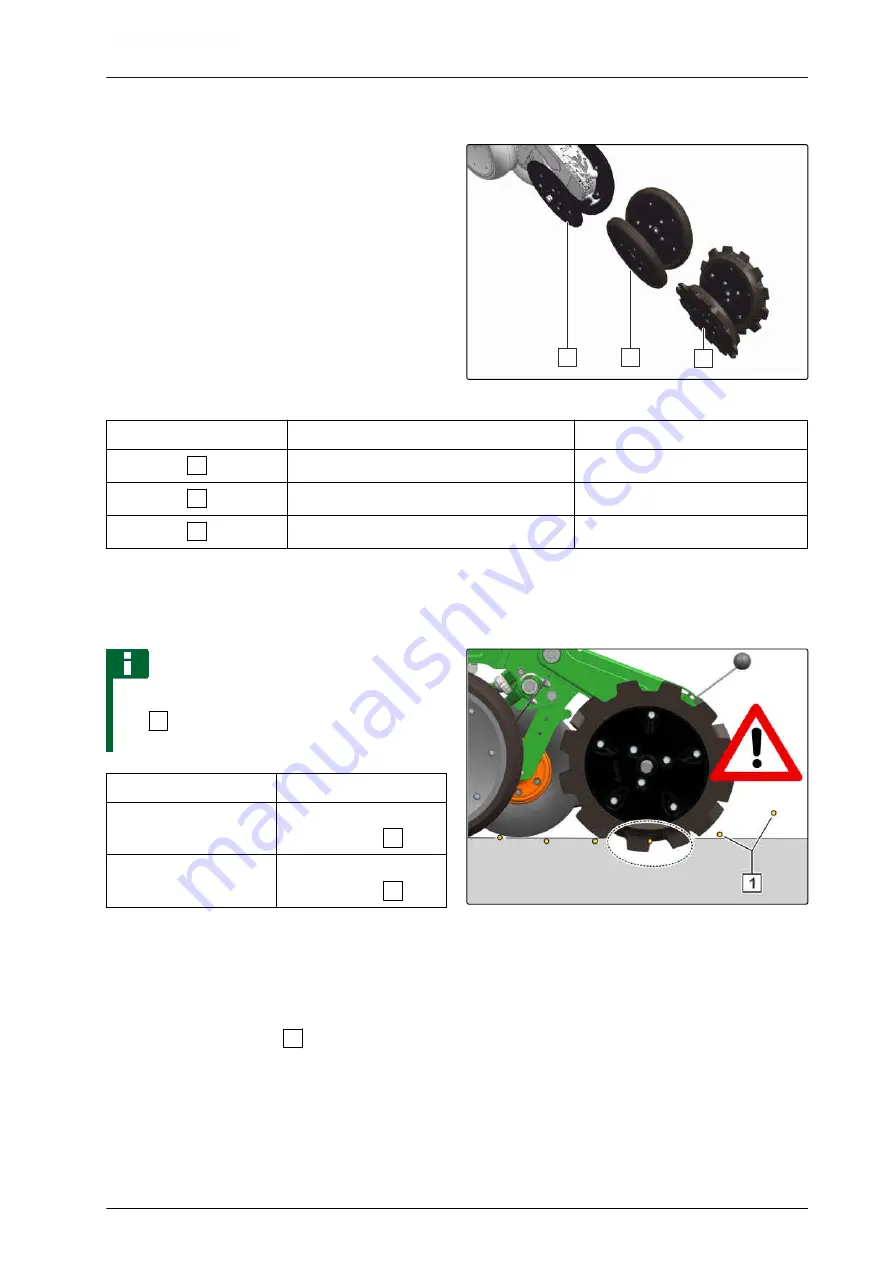
Number
V press rollers
Operating conditions
1
Smooth press rollers 350x33
Light soils
2
Smooth press rollers 350x50
Medium-heavy soils
3
Serrated press rollers 350x50
Heavy soils
The press rollers close the seed furrow. The press
roller pressure, the pitch, and the distance between
the press rollers can be adjusted.
NOTE
To ensure that the seed is not moved out of the
soil
1
, the serrated press rollers may not work
deeper than the set seed placement depth.
Operating conditions
Press roller pressure
Heavy soils
Increase the press roller
pressure:
+
Light soils
Reduce the press roller
pressure:
-
CMS-I-00002743
1.
Lift the implement.
2.
Secure the tractor and implement.
3.
Unlock the setting lever
1
.
CMS-T-00001931-F.1
6 | Preparing the machine
Preparing the implement for operation
MG6659-EN-GB | F.1 | 25.10.2022 | © AMAZONE
89


