


OSPF Configuration
©2008 Allied Telesis Inc. All rights reserved.
Software Version 5.2.1
AlliedWare Plus
TM
Operating System Software Reference C613-50003-00 REV E
29.3
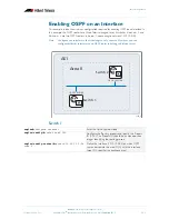
Enabling OSPF on an Interface
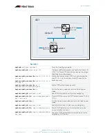
This example shows the minimum configuration required for enabling OSPF on an interface. In
this example, the OSPF routers are Allied Telesis managed Layer 3 switches.
Switch 1
and
Switch 2
are two OSPF routers in
Area 0
connecting to network 10.10.10.0/24.
Note:
Configure one interface so that it belongs to only one area. However, you can
configure different interfaces on an OSPF router to belong to different areas.
Switch 1
ospf_1
Switch 1
10.10.10.10/24
AS1
10.10.10.11/24
Area 0
Switch 2
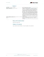
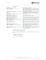
awplus#
configure terminal
Enter the
Configure
mode.
awplus(config)#
router ospf 100
Configure the Routing process and specify the Process
ID (
100
). The Process ID should be a unique positive
integer identifying the routing process.
awplus(config-router)#
network 10.10.10.0/24
area 0
Define the interface (10.10.10.0/24) on which OSPF
runs and associate the area ID (
0
) with the interface
(area ID
0
specifies the backbone area).