


Initial circuit pack installation
Powering and initial circuit pack installation for 1665 Data
Multiplexer (1665 DMX)
............................................................................................................................................................................................................................................................
365-372-304R7.1
Issue 1, November 2007
2 - 2 9
........................................................................................................................................................................................................................
6
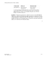
Install the SFP module per
Install pluggable transmission modules (p. 2-34)
.
........................................................................................................................................................................................................................
7
Check off the appropriate box in
Appendix E, “Installation checklist”
.
........................................................................................................................................................
E
N D
O
F
S
T E P S
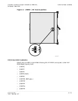
LNW67 (1G SX) installation (optional)
Follow this procedure only if installing LNW67 (1G SX) circuit packs into the 1665 DMX
shelf.
Important!
The LNW67 (1G SX) requires
multi-mode
fiber.
........................................................................................................................................................................................................................
1
Refer to the engineering job specification. Identify the proper function group slot (A1, A2,
B1, B2, C1, C2, D1, D2) and/or growth slot (G1 or G2) where the LNW67 circuit pack
will be installed.
Important!
Unless equipped with LNW59 VLF mains, the LNW67 circuit pack can
only be installed in slot 1 of any function group or growth slot 1.
........................................................................................................................................................................................................................
2
Remove the LNW67 from the packing material.
........................................................................................................................................................................................................................
3
Place the circuit pack into the shelf fn slot as required). Do
NOT
engage the circuit pack
in the backplane connector.
........................................................................................................................................................................................................................
4
Install a blank circuit pack into the companion fn circuit pack slot as required.
Important!
Blank circuit packs are required in all unused slots to provide proper air flow
for cooling.
........................................................................................................................................................................................................................
5
for each additional function group and/or growth slot to be
equipped with LNW67 circuit packs.
Summary of Contents for Data Multiplexer Explore 1665
Page 8: ... Contents v i i i 365 372 304R7 1 Issue 1 November 2007 ...
Page 12: ... List of figures x i i 365 372 304R7 1 Issue 1 November 2007 ...
Page 16: ... List of tables x v i 365 372 304R7 1 Issue 1 November 2007 ...
Page 24: ... About this document x x i v 365 372 304R7 1 Issue 1 November 2007 ...
Page 272: ... Final operations Operational tests 5 2 2 365 372 304R7 1 Issue 1 November 2007 ...
Page 326: ... Cleaning pluggable optics modules Fiber cleaning B 1 4 365 372 304R7 1 Issue 1 November 2007 ...
Page 408: ...I N 4 365 372 304R7 1 Issue 1 November 2007 Index ...