


DS3 protection switching
Installation tests
............................................................................................................................................................................................................................................................
365-372-304R7.1
Issue 1, November 2007
4 - 2 9
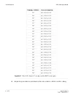
Requirement:
The ACTIVE LED on the first circuit pack remains on.
The ACTIVE LED on the second circuit pack remains off.
The FAULT LED on the second circuit pack will light for several seconds then extinguish.
On the SYSCTL, the MN alarm extinguishes.
........................................................................................................................................................................................................................
6
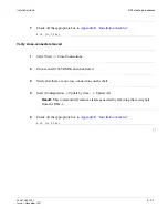
Check off the appropriate box in
Appendix E, “Installation checklist”
.
........................................................................................................................................................
E
N D
O
F
S
T E P S
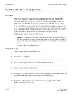
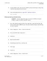
DS3 function unit protection switching test (command)
While an STS cross-connection exists, and a test set is connected, the protection switching
will be verified.
This test will initiate switching commands from the CIT and verify proper switching and
LED indications while monitoring transmission at a test set.
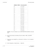
Important!
It is not necessary to perform this test on each sts cross-connection,
however this procedure should be performed on each Function Unit Slot pair.
........................................................................................................................................................................................................................
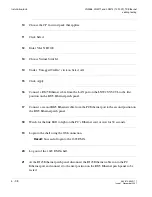
1
Select Fault -> Protection Switch...
........................................................................................................................................................................................................................
2
Click on 1+1 Equip fn-x (x is a,b,c or d corresponding to the function group equipped with
DS3).
........................................................................................................................................................................................................................
3
Click Select.
........................................................................................................................................................................................................................
4
In the Switch Type: pull-down, select Manual (Normal).
........................................................................................................................................................................................................................
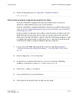
5
Click Apply.
Result:
The pack that was active should now be the standby pack and the pack that
was standby is now active. Transmission should take a momentary hit as it is switched
to the other pack. This information should agree with the ACTIVE LEDs on the
LNW16/LNW19/LNW19B, LNW18 or LNW20 circuit packs.
Summary of Contents for Data Multiplexer Explore 1665
Page 8: ... Contents v i i i 365 372 304R7 1 Issue 1 November 2007 ...
Page 12: ... List of figures x i i 365 372 304R7 1 Issue 1 November 2007 ...
Page 16: ... List of tables x v i 365 372 304R7 1 Issue 1 November 2007 ...
Page 24: ... About this document x x i v 365 372 304R7 1 Issue 1 November 2007 ...
Page 272: ... Final operations Operational tests 5 2 2 365 372 304R7 1 Issue 1 November 2007 ...
Page 326: ... Cleaning pluggable optics modules Fiber cleaning B 1 4 365 372 304R7 1 Issue 1 November 2007 ...
Page 408: ...I N 4 365 372 304R7 1 Issue 1 November 2007 Index ...