


Office alarm test
Operational tests
............................................................................................................................................................................................................................................................
365-372-304R7.1
Issue 1, November 2007
5 - 5
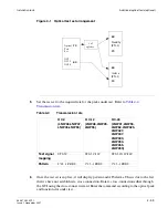
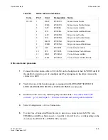
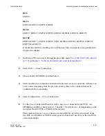
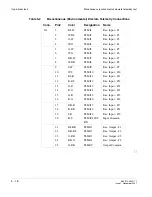
Table 5-1
Office Alarm Connections
Office alarm test procedure
........................................................................................................................................................................................................................
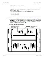
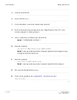
1
Connect the office alarm cable to J12 (ALM) on the backplane of the 1665 DMX shelf. If
the shelf to be tested is part of a multiple shelf bay arrangement, the office alarm cable
connects to shelf 1.
........................................................................................................................................................................................................................
2
Verify that one of the function groups is equipped with LNW6/LNW7/LNW8 DS1,
LNW16/LNW19/LNW19B DS3 or LNW18/20 TMUX circuit packs.
........................................................................................................................................................................................................................
3
Establish a CIT session by following the procedure under
Chapter 3, “Software download and circuit pack installation”
.
........................................................................................................................................................................................................................
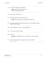
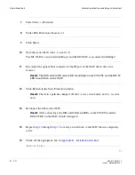
4
Select Configuration -> Cross-Connections.
........................................................................................................................................................................................................................
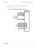
5
Use the Cross-Connection Wizard to enter a new cross-connection at the STS-1 rate,
UPSR Ring Add/Drop, between m1-1-1 and fn1-1 (fn will be a,b,c or d depending on the
slot where the DS1, DS3, or TMUX CP is located).
Conn.
Pin#
Color
Designation
Name
J12-J13
1
2
3
4
BL-W
W-BL
O-W
W-O
RYMJV1
RYMJV2
RYMJA1
RYMJA2
Minor Alarm Visible
Minor Alarm Visible Return
Minor Alarm Audible
Minor Alarm Audible Return
5
6
7
8
G-W
W-G
BR-W
W-BR
RYMNV1
RYMNV2
RYMNA1
RYMNA2
Major Alarm Visible
Major Alarm Visible Return
Major Alarm Audible
Major Alarm Audible Return
9
10
11
12
S-W
W-S
BL-R
R-BL
RYCRV1
RYCRV2
RYCRA1
RYCRA2
Critical Alarm Visible
Critical Alarm Visible Return
Critical Alarm Audible
Critical Alarm Audible Return
Summary of Contents for Data Multiplexer Explore 1665
Page 8: ... Contents v i i i 365 372 304R7 1 Issue 1 November 2007 ...
Page 12: ... List of figures x i i 365 372 304R7 1 Issue 1 November 2007 ...
Page 16: ... List of tables x v i 365 372 304R7 1 Issue 1 November 2007 ...
Page 24: ... About this document x x i v 365 372 304R7 1 Issue 1 November 2007 ...
Page 272: ... Final operations Operational tests 5 2 2 365 372 304R7 1 Issue 1 November 2007 ...
Page 326: ... Cleaning pluggable optics modules Fiber cleaning B 1 4 365 372 304R7 1 Issue 1 November 2007 ...
Page 408: ...I N 4 365 372 304R7 1 Issue 1 November 2007 Index ...