background image

© Agrowtek Inc.   |  www.agrowtek.com  |  Technology to Help You Grow™

12

Device List

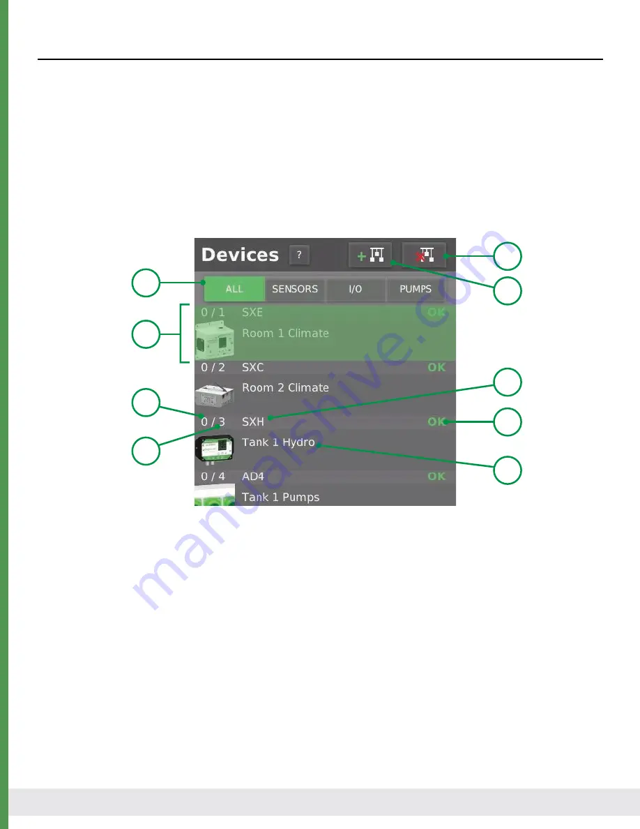
The device list comprises a list of all of the GrowNET™ devices that are connected to the GCX system. The 

device list can be organized by device type (sensor, I/O or pumps) or can show all devices (all.) This is also 

where devices are added to and removed from the system. 

Each device in the list includes basic details about the device including the type with an icon, the reference 

name, communication status and address details. Scrolling through the list of a devices at a glance can iden-

tify any offline devices.

Selecting an device in the list will highlight it and populate the properties and data relative to the device on 

the device pages for viewing and editing.

1. Device Type  


Select the type of devices to show in the list.

2. Add a Device   Press to open the “Add Device” dialog window and scan for new devices.

3. Delete a Device  

Press to delete the currently selected device from the system.

4. Product Model   Product type/model number.

5. Device Status   Communication status of the device; see chart below.

6. Device Name   Reference name assigned by the operator and used by the control functions.

7. Device Address  

The GrowNET™ device address.

8. Bus Number  The GrowNET™ bus number the device is on (100 devices per bus.)

9. Selected Device  

The selected device is highlighted in a transparent green.

8

9

4

5

7

6

3
2

1

Summary of Contents for GrowControl GCX

Page 1: ...to Help You Grow 1 Agrowtek Inc www agrowtek com Technology to Help You Grow 1 Agrowtek Inc www agrowtek com Technology to Help You Grow Technology to Help You Grow AGROWtEK INSTRUCTION MANUAL GCX GCX Cultivation Control Systems GrowControl GCX ...

Page 2: ...em Settings 27 Device Management 28 Add a Device 28 Remove a Device 30 Sort Device List 31 Change Address 32 Replace a Device 33 Device Name 34 Input Output Name 35 Where Used Search 36 Controls 37 Control Groups 38 Controls Workspace 38 Controls Toolbar 41 Adding Editing Controls 42 Enabling Control Functions 44 Control Setting Schedule 45 Control Setting Output 46 Clock Timer 47 Count Timer 48 C...

Page 3: ... available to sense and control the environment including Environment Sensors temperature humidity light co2 etc Hydroponics Sensors pH conductivity ORP etc Peristaltic Dosing Pumps Control Relays DIN Rail I O Modules GrowNET devices connect using standard CAT5 Ethernet cable and RJ 45 connections HX8 GrowNET Hubs expand one GrowNET port into eight more ports HX8 hubs provide power to the devices ...

Page 4: ...e Display Size 10 1 15 6 Display Resolution 1024x800 1920x1080 Max GrowNET Devices 100 200 Number of GrowNET Ports 8 16 GCX GCX 2 3 4 5 6 1 7 1 Conduit Knock Out Knock out for hard wired DC power input connection 2 Power Input Jack Barrel jack connection for DC power input 3 USB Slave Port Slave port for boot loader loading system firmware image from USB host 4 USB Host Ports USB Ports for WIFI me...

Page 5: ... Agrowtek Inc www agrowtek com Technology to Help You Grow 5 Dimensions GCX 11 05 11 92 10 50 10 42 3 27 Dimensions GCX 14 42 17 92 16 50 13 80 3 27 ...

Page 6: ...space around the system cool and ventilated to prevent overheating of system components Installation Instructions READ UNDERSTAND ENTIRE MANUAL PRIOR TO OPERATION Failure to read understand and comply with warnings and installation requirements may result in property damage personal injury or death Site Requirements Electrical The GCX system requires one 120Vac electrical outlet GFCI fault protect...

Page 7: ...om panel if necessary Device Connections All GrowNET devices are connected using standard CAT5 Ethernet cable with RJ 45 connections Devices can be connected directly to the GrowNET ports on the bottom of the controller or through HX8 GrowNET hubs It is typical to simplify cabling by locating hubs centrally in hall ways and rooms allowing single runs from an 8 port device hub back to a central hub...

Page 8: ...creen Press the button on the page header to display the help dialog 1 Memory Status System memory status should read OK 2 Memory Capacity Capacity and free space on the system memory 3 Message Buffer Messages showing current actions of the loader 4 Progress Bar Indicates the progress of the loader screen before starting the system 5 Skip Button The loader screen can be skipped if this button is p...

Page 9: ...en ever a text field is selected Login Screen User accounts with operator or administrator access can be configured on the system to restrict access to the system s interface If Require Login on Power up is checked the system will boot with the login screen Swipe the slider at the bottom of the screen to the right to continue 2 1 1 Logo Area A custom logo can be displayed see the Files page for mo...

Page 10: ... The right pane shows a customizable report by control group zone Page between the different groups to quickly monitor the conditions and I O status of devices in each group Devices with active outputs are highlighted green and sensors in alarm condition are highlighted red for enhanced vis ibility The main menu bar is located at the bottom of the display and is used to switch between the primary ...

Page 11: ...he name and status of each device Select the device to monitor the device or edit the device properties 3 4 1 2 Devices Menu Bar The devices menu bar selects between the monitoring page and alarms calibration and other device prop erties pages The bar indicates which page is active by highlighting the icon green and darkening the back ground Press the tabs to switch between the screen pages 1 Moni...

Page 12: ...lecting an device in the list will highlight it and populate the properties and data relative to the device on the device pages for viewing and editing 1 Device Type Select the type of devices to show in the list 2 Add a Device Press to open the Add Device dialog window and scan for new devices 3 Delete a Device Press to delete the currently selected device from the system 4 Product Model Product ...

Page 13: ...ng displayed in 5 Graph Pane Graph history pane showing 1440 points touch a pane to enlarge the graph 6 X Axis Time axis of graph panes all share the same time axis Enlarge graph for dates 5 1 2 4 3 6 Device monitor page provides the current readings of the sensor values and a graphical history for each sen sor channel The time since the last reading update is shown in the page title bar Additiona...

Page 14: ...ump 3 Manual Auto Manually set outputs pumps Off On or set to AUTO for function control 4 Output Status Graphic and info displaying the output status The device monitor page provides the output status and a graphical history for each output The time since the last reading update is shown in the page title bar Additional data can be displayed by touching on a graph pane to open the enlarged graph w...

Page 15: ...ndow 1 2 4 3 5 6 1 Position Current position reported by the MX controller 2 Output Status Graphic and info displaying the output status forward reverse or off 3 Knob Status Displays current position of the MX controller s manual override knob 4 Manual Auto Manually operate the MX controller disable or enable automatic control Automatic or manual controls are not available if the knob position is ...

Page 16: ...s stored on the system in csv format for export by USB or email see the Files section of this manual To set the data logging interval see the device management tab 1 Exit Button Press to close the graph window 2 Cursor Touch on the graph display to show cursor data newest data page only 3 Date Beginning and end dates of the data on the chart 4 Fwd Back Page Forward Backward buttons to move through...

Page 17: ... button This can aid in troubleshooting if a device is operating in an unexpected fashion Device Location To show the device in the home report view select a control group to associate it with then check the box to show it in the report 1 Device Name Reference name for the GrowNET device 2 Device Location Reference the device to a control group to display the device in the home report 3 Show in Re...

Page 18: ...ow alert values To disable the high or low alert use a value of 0 Check the Enabled box to enable the alert Alerts will only be sent once each time they are activated 1 Sensor Channel Select the sensor channel to configure the alert limits 2 High Alert If sensor value meets or exceeds this value trigger a high alert 3 Low Alert If sensor value meets or falls below this value trigger a low alert 4 ...

Page 19: ...sor channel to calibrate and follow the prompts on the display Most calibration requires the user to simply enter the actual calibrated vale 1 Channel Select the sensor channel to calibrate 2 Calibration Value Follow the prompts and enter the calibration value 3 Prompts Instructions to follow for calibration 4 Calibrate Button Press once the calibration value has been entered to save the value 5 R...

Page 20: ...ory calibrated flow rate if fluids are viscous or supply lines are long Operate the pump for 60 seconds and measure the output with a graduated cylinder Enter the measured quantity as the calibration value mL min to set the true flow of the dosing pump MX Motor Position Calibration In some cases it may be necessary to adjust the calibration of the MX controller s position to ensure it is ac curate...

Page 21: ...ctivate various management dialogs see setting up devices section 3 Logging Options Configure the logging interval and delete logs See the Files page for more advanced log management 2 1 3 4 5 1 Factory Info View the production info for a device including serial number revision etc 2 Change Order Change the order in the device list also changes polling order 3 Change Address Change the device addr...

Page 22: ...ess and hold on the control icon s 3 name to drag the function to a different order in the workspace 8 3 1 2 4 5 7 6 9 1 Workspace Controls work space shows control functions in the selected group 2 Function Toolbar Toobar of available functions press a button to add a new function to the workspace 3 Function Icon Icon depicting the function type status and name Press the function icon to open the...

Page 23: ... uses DHCP to obtain an IP address automatically from a newtwork DHCP server router If a static IP addres is preferred set a static IP address in the network router If a network connection is detected the controller s IP address will be displayed Use the INFO button to get details about the network activity 1 4 3 2 1 Ethernet Status of Ethernet connection 2 WiFi Status and configuration of wireles...

Page 24: ...alerts can be enabled See Email Configuration section for more details and instructions on using Gmail 1 Recipients Manage recipients of emails from the system 2 Text Carrier If recipient is a mobile phone number select the carrier of the phone service 3 Recipeint List List of message recipients select a recipient to highlight it 4 Delete Recipient Delete the highlighted recipient from the list 5 ...

Page 25: ...em while operator does not have access to any of the settings on the system page Users are required to log into the system on power up if the option is selected or if a user log out of the sys tem If the require login on power up option is not checked the system will not require login on power up even if users are configured on the system 1 4 2 3 1 Manage Users Add and remove users from the system...

Page 26: ...rted to be displayed on the login screen when users are logged out of the system The file must be png format and be named logo png to be imported by the system 1 6 2 3 4 5 7 8 1 System Memory Status of system memory and capacity 2 External Memory Drop down box to select the external USB memory source No External Memory Detected is shown if no USB memory is connected 3 File to Transfer Select a sys...

Page 27: ...Station Select a global weather station if equipped 4 Weather Alarms Enter weather station alarm set points for use by control functions Alarm bell icon turns RED to indicate an alarm is active 5 About Button Opens the about dialog with system version number and revision history 6 Time Zone Select the time zone that the system is located in Time is automatically updated by internet time services 7...

Page 28: ...ress number between 1 100 Addresses are automati cally selected based on the next available address when they are added to the system or an address may be specified from available addresses Add a Device New devices must be added one at a time to the system unless devices are pre addressed prior to adding them to the system If multiple new devices are connected to the system without adding them one...

Page 29: ...ress to assign 7 If desired modify the device name then press SAVE The device will now be shown in the system device list Select the device in the list to monitor the device or modify the device properies 4 The Add Device dialog will pop up Select the device bus to scan 5 Press the START SEARCH button and the system will search the bus for new devices ...

Page 30: ...n the system The device will be deleted from the device list and the data logs will be erased from the system memory Remove a Device If a device is no longer in use on a system it can be deleted from the device list NOTE Removing a device that is in use by control functions will disable the control function If the device is still connected and communicating with the system it should be de comissio...

Page 31: ...matically populated at the top of the list It may be desirable to sort the new device to a different order in the list To organize the device list 1 Select the ALL button to show all devices in the device list 2 Press the CHANGE ORDER button to open the change order dialog 3 When the dialog opens select the location in the list to move the device to 4 Press MOVE DEVICE to perform the move operatio...

Page 32: ...gnment on the device and in the system device list NOTE Changing the address will create a new data log file and erase the previous log data To change a device address 1 Press the CHANGE ADDRESS button to open the change address dialog 2 Select a new address from the list of available addresses not in use on the bus 3 Press SET ADDRESS to confirm the new address ...

Page 33: ...need to review the controls and update the assignments to the replacement device 1 Leave the offline device on the system do not remove it 2 Add a new device the replacement following the Add a Device procedure on previous pages 3 Select the new device and press the REPLACE DEVICE button to open the replace device dialog 4 Select the offline device you want to replace with the new device 5 The new...

Page 34: ...e name is used in Control function programming Data log files Alert messages Device names can be assigned in the Add Device dialog or can be edited on the device information page 1 Select the device and then select the device name text field 2 A keyboard will appear enter the new name 3 Press the save button to save the new name to the system memory 1 3 2 ...

Page 35: ...e I O names Relays RX DX Motor Controllers MX Valve Controllers VX Dosing Pumps AD Each output should be named to describe what is connected to the input output or pump head The descriptions are used to configure the control functions To set an input output name 1 Select the output or input channel to edit 2 Enter the new name 3 Press the save button to store the new name in system memory ...

Page 36: ...d to help a user identify the control functions that are assigned to a spe cific input or output This can then be used to identify potential sources of problems or ensure the output is properly assigned to the correct functions To search where an input or output is used 1 Select the output to search 2 Press the search icon 1 2 3 The search results dialog is shown indicating the control group and c...

Page 37: ...Control Workspace Control Functions Control functions are how logic is created to control equipment in a growing environment A variety of con trol functions are available to create simple or complex nested logic by linking functions together The controls page has three main areas 1 Workspace Bar Select and edit the properties of the workspace 2 Toolbar Add functions to the workspace by pressing th...

Page 38: ... bar at the top of the controls page 5 1 2 4 3 6 1 Run Pause Open a dialog to place the group into run or pause mode 2 Current Group Select which control group workspace to show 3 Rename Group Open a dialog to rename the current control group 4 Add Group Open a dialog to add a new control group to the system 5 Move Group Open a dialog to move the current control group in the list order 6 Delete Gr...

Page 39: ...used Functions are suspended in their current status state Any outputs controlled by the functions will no longer be operated by the functions Any dosing pumps will complete their current dose and then suspend dosing Run Pause Mode 1 3 2 Press the run pause button to open the dialog confirm you wish to pause the control group execution When the control group is paused the run pause button 1 and wo...

Page 40: ...Function Button Icon depicts the type of control function see the tool bar for reference 2 Function Name The function name set by the user is shown under the function button 3 Function Status The status of each function is shown in the upper left with a colored dot Each function that is added to the workspace has it s own button icon in the workspace The button icons include information about the ...

Page 41: ... a humidifier or dehumidifier 6 Photostat Photo sensitive control to operating an output device based on solar light levels For light dimming in conjuction with the sun use the LIGHTS function 7 CO2 Standard ppm based CO2 injection or exhaust control function with set point and dead band Con trol a discrete relay for a CO2 valve or burner for injection or an exhaust fan or alarm horn for high CO2 ...

Page 42: ... workspace is pressed the function editor is opened The function editor is where set tings are configured for the function including the scheduling set points and device assignments The layout of the function editor is generally the same for all functions with the settings area having unique fields and options for each type of control function 1 Header Bar General operations including function nam...

Page 43: ...must not be empty or the changes to the control function can not be saved 3 Delete Function Open a dialog to delete the current control function from the workspace 4 Save Settings Press the save button to save the changes to the system memory The save button will be highlighted green when settings on the page have changed 5 Exit Editor Closes the editor dialog and returns to the workspace If chang...

Page 44: ...selected function status is true active or false idle To coordinate a function with the status of another device the setting can be configured to be enabled only if an output is currently on or currently off 1 Press the IF OUTPUT button in the desired on or off mode The Enable Mode area will expand and the drop down menus to select an output will be displayed 2 Select an output device 3 Select an ...

Page 45: ...o set a date range for the setting to be enabled 3 First Day First date that the setting will be enabled date range mode 4 Last Day Last date that the setting will be enabled date range mode 5 Start Time Time of day that the setting will be enabled time range mode 5 End Time Time of day that the setting will be disabled time range mode 1 2 3 5 4 6 To enable a function setting dependent on another ...

Page 46: ...t is located on 3 Output Select the equipment output to be controlled 4 Output Mode Select if the function should turn the output on or off when activated None The function will be status only Discrete The function will operate a discrete on off output Analog The function will operate an analog output Discrete on off Output 1 2 3 1 Device Select the GrowNET device that the output is located on 2 O...

Page 47: ...ned 1 2 3 1 Enable Mode Select a mode to enable the timer function 2 Schedule Time Range Enter the start and end time for the timer function Date Range Set dates if the setting should be active only during a date range 3 Function Output Select a function output type if desired A None type will not act on an output but will still set a function status In the example above the timer is enabled witho...

Page 48: ...1 2 5 3 4 6 1 Delay On If the function is enabled activate the function after the preset delay has elapsed 2 Delay Off Keep the function activated for the preset delay after the function is disabled 3 One Shot On Activate the function for a preset time when the function is enabled 4 One Shot Off Activate the function for a preset time when the function is disabled Enable Input On Delay Off Delay O...

Page 49: ...t Time duration for the off period of the cycle 3 Discrete Output Select the device and output for the cycle timer to operate on Cycle timers only operate on discrete type outputs 4 Preview A preview of the timer actions is shown in this field 5 Units Select the units for the off and on presets seconds minutes or hours 1 2 5 3 4 Seconds 65500 Minutes 1092 Hours 18 Maximum time values NOTE To ensur...

Page 50: ...ivates when temperature is below setpoint 2 Sensor Temperature sensor input to evaluate the set point against 3 Setpoint The target sensor value to achieve 4 Deadband The allowed drift from the target before taking action to return to the target 5 Preview A preview of the function settings NOTE When configuring a thermostat on HVAC systems it is recommended to control the heat or cool output from ...

Page 51: ...rget before activating the humidistat to return the reading to the target Example uses Dehumifiers Exhaust fans Humidifiers Misters 1 2 5 3 4 1 Mode Dehumidify Function activates when humidity exceeds setpoint Humidify Function activates when humidity is below setpoint 2 Sensor Humidity sensor input to evaluate the set point against 3 Setpoint The target sensor value to achieve 4 Deadband The allo...

Page 52: ... the light intensity returns to the target the photostat is de activated Example uses Activate fans with high sunlight for pre emtpive cooling Alarms 1 2 5 3 4 1 Mode High Light Function activates when light intensity exceeds setpoint Low Light Function activates when light intensity is below setpoint 2 Sensor Light sensor input to evaluate the set point against 3 Setpoint The target sensor value ...

Page 53: ...ation is below setpoint 2 Sensor CO2 ppm sensor input to evaluate the set point against 3 Setpoint The target sensor value to achieve 4 Deadband The allowed drift from the target before activating the function 5 Dark Switch Disables injection when the CO2 sensor unit detects the ambient light level is 0 6 Preview A preview of the function settings NOTE When configuring a CO2 control for injection ...

Page 54: ... a control mode discrete or dimmable Configure the output assignments and if the light is dimmable set the the target intensity and ramp rate It is possible to configre both a discrete output for controlling mains circuit power and a dimmable output for controlling intensity 1 Discrete Mode Enables discrete on off output control 2 Discrete Output Select a device and output on the device to operate...

Page 55: ...ll be dimmed until the target is reached If sunlight exceeds the target the lights will dim to off if the light intensity remains above the target without supple mental light Using a sensor exposed only to the sun outdoor weather station will result in the lights dimming to off when the sunlight intensity is above the target and will not dim when the sunlight intensity is below the target Temperat...

Page 56: ...imit high and low slider positions If a static fixed position is desired turn on the switch and set the position The control setting will set the MX1 position to this static value when the setting is enabled 1 2 3 4 5 1 Motor Controller Select the motor controller this setting will operate on 2 Vent Shade Mode Select if the motor is for ventilation or shading 3 Position Limits Minimum and maximum ...

Page 57: ... reduce solar heating or when the interior temperature is too high can help alleviate excess heat 1 Solar Shading Set this option to limit the position based on light intensity If intensity is high the shade will reduce open to the selected position 2 Light Sensor Select the sensor to read the light intensity 3 Solar Position Maximum open position when limit is exceeded 4 Solar Limit Light intensi...

Page 58: ... excess heat 1 Solar Venting Set this option to limit the position based on light intensity If intensity is high the shade will reduce open to the selected position 2 Light Sensor Select the sensor to read the light intensity 3 Solar Position Maximum open position when limit is exceeded 4 Solar Limit Light intensity high limit if reached the position limit is activated 5 Temperature Staging Set th...

Page 59: ...move the sliders to the desired posi tions TIP To disable a specific weather override position set the position to 100 This will prevent the override from reducing the position even if the alarm is active 2 3 4 1 1 Weather Positions Set this option to limit the position based on system weather alarms 2 Rain Position Sets the maximum position allowed during a rain alarm 3 Wind Position Sets the max...

Page 60: ...vel if a moisture sensor is connected 4 1 6 3 2 5 1 Add Stage Adds a new irrigation stage to the function setting 2 Remove Stage Deletes the currently seleted stage from the function settings 3 Stage Select the stage number to edit or remove 4 Stage Feed Time Duration to run the stage output for irrigation 5 Stage Output Stage output device and channel irrigation valve 6 Repeat Settings If the irr...

Page 61: ...gs 2 Output Settings Set the output device and output channel that the pump valve is connected to 3 On Delay Seconds delay to wait after the zone valve is opened before operating the feed pump main valve 4 Discrete Output Sets a discrete on off type of output to operate the pump valve 5 Analog Output Sets an analog vaiable type of output to operate the pump valve Drain Valve A drain valve can be i...

Page 62: ...If no time range is set then the function may activate any time the sensor output is low and will require the user to ensure the system can irrigate until the trigger level is restored 1 Enable Tirggering Enable the switch to show and configure the trigger settings 2 Input Settings Set the input device and input channel that the sensor is connected to 3 Trigger Preset Set the mV reading from the s...

Page 63: ... Mode Fill Activates when water level is low to return to the high position Drain Activates when water level is high to return the to low postion 2 Time out Time limit for the fill or drain event to prevent over fill or drain lock out 2 3 4 1 1 High Sensor Select the input device and channel of the high level sensor 2 Low Sensor Select the input device and channel of the low level sensor 3 Fill Dr...

Page 64: ...ting is enabled it will monitor the sensor readings and compare them to the recipe If the recipe dictates a correction the function will operate the assigned dosing pumps Recipes can contain up to 24 nutrient parts Hydroponics Sensor 1 Select the hydroponics sensor unit 1 that the dosing function will use to read the pH conductivity EC and other water properties A hydroponics sensor must be connec...

Page 65: ...sary by using the sort buttongs 4 to move the selected pump up or down in the list 1 Dosing Pump Device Select the device that has the desired chemical pump head on it 2 Pump Head Select the pump head on the pump device 3 Pump List List of dosing pumps by pump name description Corresponding recipe part name is shown in parenthesis 4 Sort Buttons Use the sort buttons to move the selected pump up or...

Page 66: ...vice that has the desired chemical pump heads on it 2 pH Up Dosing Enable the switch to show the configuration settings 3 pH Down Dosing When enabled the dosing pump head and flow rate settings are shown 4 ORP Dosing Enable the switch for ORP dosing settings 5 Pump Head Select an available pump head on the pump device for the dosing mode 6 Flow Rate Flow rate for the respective pump head to dose a...

Page 67: ...ditor is where new recipes can be created or existing recipes can be modified 1 Editor Controls Select the recipe to edit or use the buttons to create or delete recipes 2 Targets Enable dosing modes and set the sensor target values and deadbands 3 Nutrient Parts Editor area for nutrient recipe Recipe Editor The recipe editor screen is divided into three main sections 1 3 2 ...

Page 68: ...ion 3 Clear Name Erases the existing name for entry of a new name 4 Delete Recipe Deletes the currently selected recipe 5 Add Recipe Adds a new blank recipe to the system 6 Save Saves the current recipe settings to memory Targets Dosing targets are compared to the sensor readings for pH conductivity nutrients and ORP If the targets are outside of the allowed drift range the recipe will activate th...

Page 69: ...rder in the part list 1 1 Nutrient Part List List of all the nutrient parts in the recipe Select a part to edit the values 2 Part Name Reference name of the recipe part 3 Dosing Group Select a group for the nutrient part groups are dosed sequentially 4 Dose Size Dose size per manufacturer recipe ml gal 5 Mix Delay Delay after dosing before moving to the next group 6 Sort Buttons Move the selected ...

Page 70: ...NC client applications that can run on any device RealVNC TigerVNC TightVNC UltraVNC Mocha VNC Lite noVNC UltraVNC Agrowtek currently recommends the free Real VNC viewer application A VNC application can connect directly to the controller s local IP address when the vnc viewer application has access to the local network If a pc or phone is connected to the wifi or Ethernet network that the con tro...

Page 71: ...y move the mouse to the upper left corner of the screen to align the pointers on the devices Access to the system outside of the local network via the internet requires port forwarding to be config ured on the network router to allow access to the VNC server on the controller A static IP address should be assigned to the controller in the network router An external port should be opened and direct...

Page 72: ...t list type an address and press ADD 2 Configure the account settings SSL and SMTP are required 3 Press the TEST button to send a test message and check if the email settings are properly configured Using Gmail Gmail requires an app password to be generated to allow applications to use the account To generate app passwords the account must have two factor authentication enabled 1 Log into your goo...

Page 73: ...l 5 From the Select device drop down choose Other custom name 6 Enter a name for reference then click the GENERATE button to create the app password 7 Use the password in the yellow box in place of your account password in the email account settings 3 An app password may now be created click App passwords ...

Page 74: ... a new update is available press DOWNLOAD UPDATE to download it to the system 3 When the download completes press REBOOT to restart the system Firmware Update Agrowtek occasionally releases updates to system firmware that add new features or resolve bugs Firmware may be updated via the internet if an internet connection is available or by USB memory A system reboot is required to complete a firmwa...

Page 75: ...tem If the firmware file is not detected by the Sys tem Loader then please try another USB flash drive or another format when formatting the flash drive Recommended Format Fat16 USB File USB memory will retain the update file so that it may be used on multiple machines without loss of the file Remove the USB memory after the update or the loader will update the firmware on each boot 4 In the Resta...

Page 76: ... ABOUT button Check the firmware version matches the expected new version When the GCX system boots up the system loader checks If new firmware has been downloaded from the internet If new firmware is found on a USB memory source If firmware is found from either source it will update the system with the firmware found System Firmware Loader ...

Page 77: ...or Quad Core 1 2GHz ARM OS Linux Operating System Memory 8GB Industrial Flash RAM 1GB 512MB shared GPU memory Enclosure Powder Coated Aluminum Working Environment Maximum 70 RH non condensing Avoid direct sunlight Specifications Technical Information Storage Store equipment in a clean dry environment with ambient temperature between10 50 C Disposal This indsutrial control equipment may contain tra...

Page 78: ...tions or environments including but not limited to high humidity or high temperature conditions The products which have been claimed and comply with the aforementioned restrictions shall be replaced or repaired at the sole discretion of the Agrowtek Inc at no charge This warranty is provided in lieu of all other warranty provisions express or implied It is including but not limited to any implied ...

Reviews: