Electrical Interfaces
AGD155 Product Manual Rev.2.2
Page 33
Note – Incremental encoder interface details
Each differential-pair includes a built-in 120
Ω
terminator and the required hardware
circuits to detect a disconnected encoder cable. When a disconnected encoder cable is
detected, the controller will disable the motor. The detection is done on the A and B
channels only (not on the index or Z-channel).
By default, the product does not support single-ended encoder. For use of single-ended
encoder, contact Technical Support.
Note – 5V supply limitation
The maximum current available for the encoder is 0.5 A.
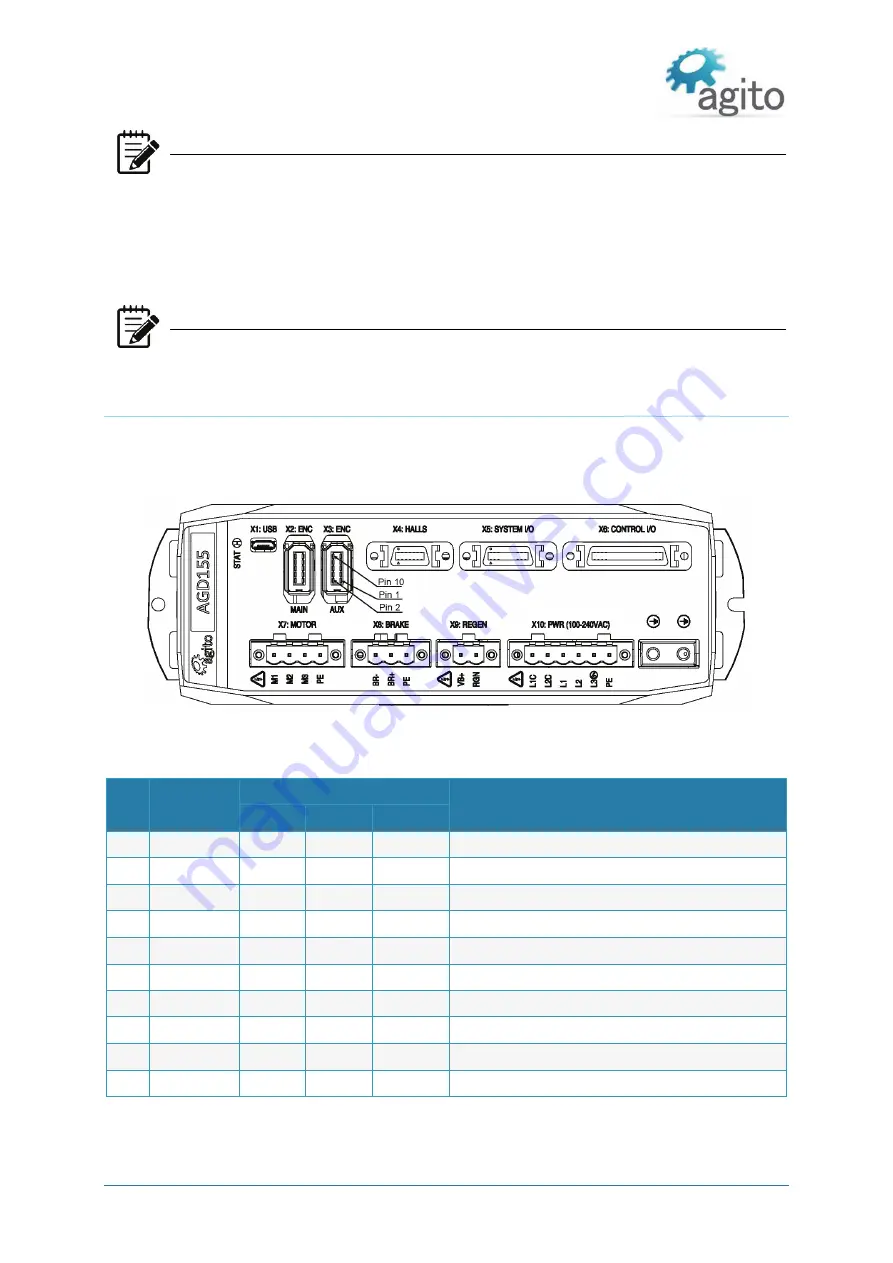
3.4.12 Interface X3: Auxiliary Encoder
The X3 encoder port is designed to interface with an auxiliary (second) encoder for the axis. It is
similar to the main encoder port, supporting digital quadrature incremental encoder, absolute BiSS-C
and absolute EnDat2.2 encoder. However, it does not support analog sin/cos encoder input
.
Figure 21 Aux Encoder Connector
Connector X3: ENC (AUX)
Pin # Name
Encoder Types
Description
AqB
BiSS-C
EnDat 2.2
1
5V
5V power supply (limited to 0.5A per connector)
2
GND
5V return and reference for differential signals
3
En
CLOCK+ CLOCK+ Clock+ pin for absolute encoders
4
Encoder_1-
CLOCK- CLOCK-
Clock- pin for absolute encoders
5
En A+
A+ (for AqB)
6
Encoder_2- A-
A- (for AqB)
7
En B+
B+ (for AqB)
8
Encoder_3- B-
B- (for AqB)
9
En Z+
DATA+ DATA+
Data+ for absolute encoders, or Z+ for AqB
10 Encoder_4- Z-
DATA- DATA-
Data- for absolute encoders, or Z- for AqB


