Service Guide E8364-90038
7-5
PNA Series Microwave Network Analyzers
Repair and Replacement Procedures
E8362C, E8363C, E8364C
Removal and Replacement Procedures
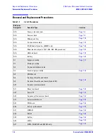
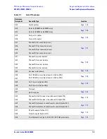
A22
Switch splitter
Page 7-44
A23
Detector (E8363C and E8364C only)
Page 7-48
A24
Detector (E8363C and E8364C only)
A25
Test port 1 coupler
Page 7-50
A26
Test port 2 coupler
A27
Channel A first converter (mixer)
Page 7-52
A28
Channel R1 first converter (mixer)
A29
Channel R2 first converter (mixer)
A30
Channel B first converter (mixer)
A31
Channel A receiver module
Page 7-54
A32
Channel R1 receiver module
A33
Channel R2 receiver module
A34
Channel B receiver module
A35
Receiver motherboard
Page 7-56
A36
Port 1 60-dB source step attenuator (Option UNL)
Page 7-58
A37
Port 2 60-dB source step attenuator (Option UNL)
A38
Port 1 bias tee (Option UNL)
Page 7-60
A39
Port 2 bias tee (Option UNL)
A40
Not used.
A41
Hard disk drive
Page 7-62
A43
Channel A 35-dB receiver step attenuator (Option 016)
Page 7-70
A44
Channel B 35-dB receiver step attenuator (Option 016)
A45
Channel R1 reference channel transfer switch (Option 081)
Page 7-72
A46
Channel R1 reference channel transfer switch (Option 081)
A47
RF path coupler (Option H11)
Page 7-74
A48
LO path coupler (Option H11)
A49
IF multiplexer board (part of A31, A32, A33, A34 procedure)
Page 7-54
Table 7-1
List of Procedures
Reference
Designator
Assembly Type
Location
Summary of Contents for E8362C
Page 11: ...Service Guide E8364 90038 1 1 1 Safety and Regulatory Information ...
Page 21: ...Service Guide E8364 90038 2 1 2 General Product Information ...
Page 33: ...Service Guide E8364 90038 3 1 3 Tests and Adjustments ...
Page 81: ...Service Guide E8364 90038 4 1 4 Troubleshooting ...
Page 137: ...Service Guide E8364 90038 5 1 5 Theory of Operation ...
Page 171: ...Service Guide E8364 90038 6 1 6 Replaceable Parts ...
Page 257: ...Service Guide E8364 90038 7 1 7 Repair and Replacement Procedures ...
Page 341: ...Service Guide E8364 90038 8 1 8 General Purpose Maintenance Procedures ...


