


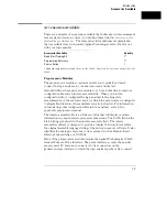


General-Purpose Probing System Description
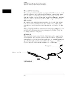
The standard probing system provided with the logic analyzer consists of a
probe tip assembly, probe cable, and grabbers. Because of the passive design
of the probes, there are no active circuits at the outer end of the cable. The
rest of this chapter is dedicated to general-purpose probing.
The passive probing system is similar to the probing system used with
high-frequency oscilloscopes. It consists of a series RC network
(90 k
Ω
in parallel with 8 pF) at the probe tip, and a shielded, resistive
transmission line. The advantages of this system include the following:
•
250
Ω
in series with 8-pF input capacitance at the probe tip for minimal
loading.
•
Signal ground at the probe tip for high-speed timing signals.
•
Inexpensive, removable probe tip assemblies.
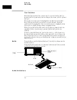
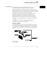
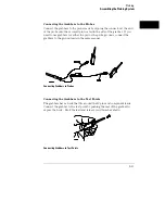
Probe Tip Assemblies
Probe tip assemblies allow you to connect the logic analyzer directly to the
target system. This general-purpose probing is useful for discrete digital
circuits. Each probe tip assembly contains 16 probe leads (data channels),
1 clock lead, a pod ground lead, and a ground tap for each of the 16 probe
leads.
Probe Tip Assembly
Probing
General-Purpose Probing System Description
2–5
Summary of Contents for 1660A Series
Page 5: ...vi...
Page 14: ...1 Introduction...
Page 24: ...2 Probing...
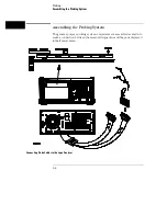
Page 35: ...Probing Assembling the Probing System 2 12...
Page 36: ...3 Using the Front Panel Interface...
Page 65: ...3 30...
Page 66: ...4 Using the Mouse and the Optional Keyboard...
Page 74: ...5 Connecting a Printer...
Page 91: ...5 18...
Page 92: ...6 Disk Drive Operations...
Page 118: ...7 The RS 232C GPIB and Centronix Interface...
Page 121: ...RS 232 GPIB Menu Map Cont The RS 232C GPIB and Centronix Interface 7 4...
Page 123: ...Printer Controller Menu Map Cont The RS 232C GPIB and Centronix Interface 7 6...
Page 132: ...8 The System Utilities...
Page 137: ...9 The Common Menu Fields...
Page 150: ...9 14...
Page 151: ...10 The Configuration Menu...
Page 159: ...11 The Format Menu...
Page 161: ...Format Menu Map The Format Menu 11 3...
Page 194: ...11 36...
Page 195: ...12 The Trigger Menu...
Page 198: ...Trigger Menu Map The Trigger Menu 12 4...
Page 199: ...Trigger Menu Map Continued The Trigger Menu 12 5...
Page 235: ...13 The Listing Menu...
Page 237: ...Listing Menu Map The Listing Menu 13 3...
Page 260: ...13 26...
Page 261: ...14 The Waveform Menu...
Page 263: ...Waveform Menu Map The Waveform Menu 14 3...
Page 264: ...Waveform Menu Map cont The Waveform Menu 14 4...
Page 300: ...14 40...
Page 301: ...15 The Mixed Display Menu...
Page 306: ...15 6...
Page 307: ...16 The Chart Menu...
Page 310: ...Chart Menu Map The Chart Menu 16 4...
Page 311: ...Chart Menu Map cont The Chart Menu 16 5...
Page 336: ...16 30...
Page 337: ...17 The Compare Menu...
Page 340: ...Compare Menu Map The Compare Menu 17 4...
Page 355: ...18 Error Messages...
Page 363: ...19 Specifications and Characteristics...
Page 377: ...20 Operator s Service...
Page 386: ...Troubleshooting Flowchart 1 Operator s Service To use the flowcharts 20 10...
Page 387: ...Troubleshooting Flowchart 2 Operator s Service To use the flowcharts 20 11...


