


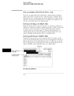


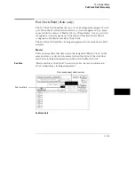


Timing Acquisition Mode Field (Timing only)
The Timing Acquisition Mode field displays the acquisition type, the channel
width, and sampling speed of the present acquisition mode. The Timing
Acquisition Mode field is used to access an acquisition mode selection menu.
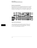
Conventional Acquisition Mode
In Conventional Acquisition Mode the analyzer stores measurement data at
each sampling interval.
Conventional Full Channel 250 MHz
The total memory depth is
4 Kbytes with data being sampled and stored as often as 4 ns.
Conventional Half Channel 500 MHz
The total memory depth is
8 Kbytes with data being sampled and stored as often as 2 ns.
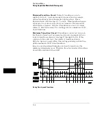
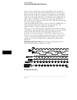
Glitch Acquisition Mode
In Glitch Acquisition Mode, a glitch is defined as a pulse with a minimum
width of 3.5 ns and a maximum width of 8 ns, or the sample period,
whichever is larger. As an example, if the sample period is 8 ns, then a glitch
is defined as being between 3.5 ns and 8 ns. One advantage of the glitch
mode is that if you expand the sample rate, a pulse that is less than the
sample rate will still be displayed as a vertical dashed line.
Glitch Half Channel 125 MHz
The total memory depth is split
between data storage and glitch storage. Data acquisition memory depth
is 2048 per channel. Glitch storage is 2 Kbytes per channel. Data is
sampled for new transitions every 8 ns.
Glitch in a Timing Waveform
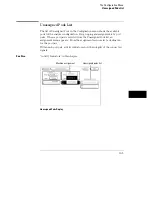
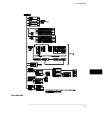
The Format Menu
Timing Acquisition Mode Field (Timing only)
11–5
Summary of Contents for 1660A Series
Page 5: ...vi...
Page 14: ...1 Introduction...
Page 24: ...2 Probing...
Page 35: ...Probing Assembling the Probing System 2 12...
Page 36: ...3 Using the Front Panel Interface...
Page 65: ...3 30...
Page 66: ...4 Using the Mouse and the Optional Keyboard...
Page 74: ...5 Connecting a Printer...
Page 91: ...5 18...
Page 92: ...6 Disk Drive Operations...
Page 118: ...7 The RS 232C GPIB and Centronix Interface...
Page 121: ...RS 232 GPIB Menu Map Cont The RS 232C GPIB and Centronix Interface 7 4...
Page 123: ...Printer Controller Menu Map Cont The RS 232C GPIB and Centronix Interface 7 6...
Page 132: ...8 The System Utilities...
Page 137: ...9 The Common Menu Fields...
Page 150: ...9 14...
Page 151: ...10 The Configuration Menu...
Page 159: ...11 The Format Menu...
Page 161: ...Format Menu Map The Format Menu 11 3...
Page 194: ...11 36...
Page 195: ...12 The Trigger Menu...
Page 198: ...Trigger Menu Map The Trigger Menu 12 4...
Page 199: ...Trigger Menu Map Continued The Trigger Menu 12 5...
Page 235: ...13 The Listing Menu...
Page 237: ...Listing Menu Map The Listing Menu 13 3...
Page 260: ...13 26...
Page 261: ...14 The Waveform Menu...
Page 263: ...Waveform Menu Map The Waveform Menu 14 3...
Page 264: ...Waveform Menu Map cont The Waveform Menu 14 4...
Page 300: ...14 40...
Page 301: ...15 The Mixed Display Menu...
Page 306: ...15 6...
Page 307: ...16 The Chart Menu...
Page 310: ...Chart Menu Map The Chart Menu 16 4...
Page 311: ...Chart Menu Map cont The Chart Menu 16 5...
Page 336: ...16 30...
Page 337: ...17 The Compare Menu...
Page 340: ...Compare Menu Map The Compare Menu 17 4...
Page 355: ...18 Error Messages...
Page 363: ...19 Specifications and Characteristics...
Page 377: ...20 Operator s Service...
Page 386: ...Troubleshooting Flowchart 1 Operator s Service To use the flowcharts 20 10...
Page 387: ...Troubleshooting Flowchart 2 Operator s Service To use the flowcharts 20 11...


