


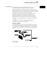


Logic Analyzer Description
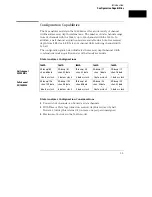
The Agilent Technologies 1660A Series Logic Analyzers are part of a
new generation of general-purpose logic analyzers. The 1660A Series
consists of five different models ranging in channel width from 34
channels to 136 channels. State speed is either 50-MHz or 100-MHz
(depending on the model), and all models have 500-MHz timing
speeds. The 1660A series logic analyzers are designed as full-featured
stand-alone instruments for use by digital and microprocessor
hardware and software designers. All models have GPIB, RS-232C,
and/or Centronix interfaces for hard copy printouts and control by a
host computer.
•
The 1660A has 100-MHz state speed, 130 data channels, six
data/clock channels, and both GPIB/RS-232C interfaces.
•
The 1661A has 100-MHz state speed, 96 data channels, six
data/clock channels, and both GPIB/RS-232C interfaces.
•
The 1662A has 100-MHz state speed, 64 data channels and four
data/clock channels, and both GPIB/RS-232C interfaces.
•
The 1663A has 100-MHz state speed, 32 data channels, two
data/clock channels, and both GPIB/RS-232C interfaces.
•
The 1664A has 50-MHz state speed, 32 data channels, two
data/clock channels, and a Centronix interface (GPIB/RS-232C
available as options).
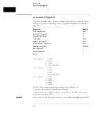
Memory depth is 4 Kbytes per channel in all pod pair groupings, or
8 Kbytes per channel on one pod of a pod pair (half channel mode).
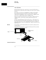
Measurement data is displayed as data listings and waveforms, and
can also be plotted on a chart or compared to a reference image.
The 50/100-MHz state analyzer has master, master/slave, and
demultiplexed clocking modes available. Measurement data can be
stamped with state or time tags. For triggering and data storage, the
state analyzer uses 12 sequence levels with two-way branching, 10
pattern resource terms, 2 range terms, and 2 timers.
1–2
Summary of Contents for 1660A Series
Page 5: ...vi...
Page 14: ...1 Introduction...
Page 24: ...2 Probing...
Page 35: ...Probing Assembling the Probing System 2 12...
Page 36: ...3 Using the Front Panel Interface...
Page 65: ...3 30...
Page 66: ...4 Using the Mouse and the Optional Keyboard...
Page 74: ...5 Connecting a Printer...
Page 91: ...5 18...
Page 92: ...6 Disk Drive Operations...
Page 118: ...7 The RS 232C GPIB and Centronix Interface...
Page 121: ...RS 232 GPIB Menu Map Cont The RS 232C GPIB and Centronix Interface 7 4...
Page 123: ...Printer Controller Menu Map Cont The RS 232C GPIB and Centronix Interface 7 6...
Page 132: ...8 The System Utilities...
Page 137: ...9 The Common Menu Fields...
Page 150: ...9 14...
Page 151: ...10 The Configuration Menu...
Page 159: ...11 The Format Menu...
Page 161: ...Format Menu Map The Format Menu 11 3...
Page 194: ...11 36...
Page 195: ...12 The Trigger Menu...
Page 198: ...Trigger Menu Map The Trigger Menu 12 4...
Page 199: ...Trigger Menu Map Continued The Trigger Menu 12 5...
Page 235: ...13 The Listing Menu...
Page 237: ...Listing Menu Map The Listing Menu 13 3...
Page 260: ...13 26...
Page 261: ...14 The Waveform Menu...
Page 263: ...Waveform Menu Map The Waveform Menu 14 3...
Page 264: ...Waveform Menu Map cont The Waveform Menu 14 4...
Page 300: ...14 40...
Page 301: ...15 The Mixed Display Menu...
Page 306: ...15 6...
Page 307: ...16 The Chart Menu...
Page 310: ...Chart Menu Map The Chart Menu 16 4...
Page 311: ...Chart Menu Map cont The Chart Menu 16 5...
Page 336: ...16 30...
Page 337: ...17 The Compare Menu...
Page 340: ...Compare Menu Map The Compare Menu 17 4...
Page 355: ...18 Error Messages...
Page 363: ...19 Specifications and Characteristics...
Page 377: ...20 Operator s Service...
Page 386: ...Troubleshooting Flowchart 1 Operator s Service To use the flowcharts 20 10...
Page 387: ...Troubleshooting Flowchart 2 Operator s Service To use the flowcharts 20 11...


