


63
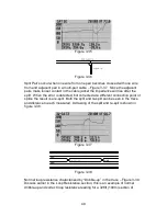
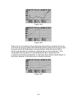
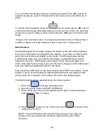
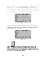
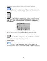
2. If Start Distance other than zero is entered and Test Lead Null is turned ON at
the same time, the Test Lead Null will take effect after the Start Distance (off-
set). Example: With a Range set to 20ft (5m), a Start Distance of 10ft (3m) is
entered, and Test Lead Null of approximately 3ft (1m), the display will actually
start at approximately 13ft (4m). A cursor placed at the far left of the plot display
will show the 10ft (3m) of off-set, but not the 3ft (1m) of Test Lead Null. See
figure 3-56.
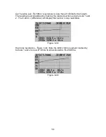
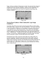
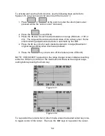
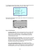
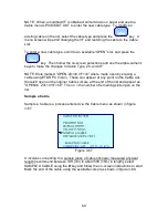
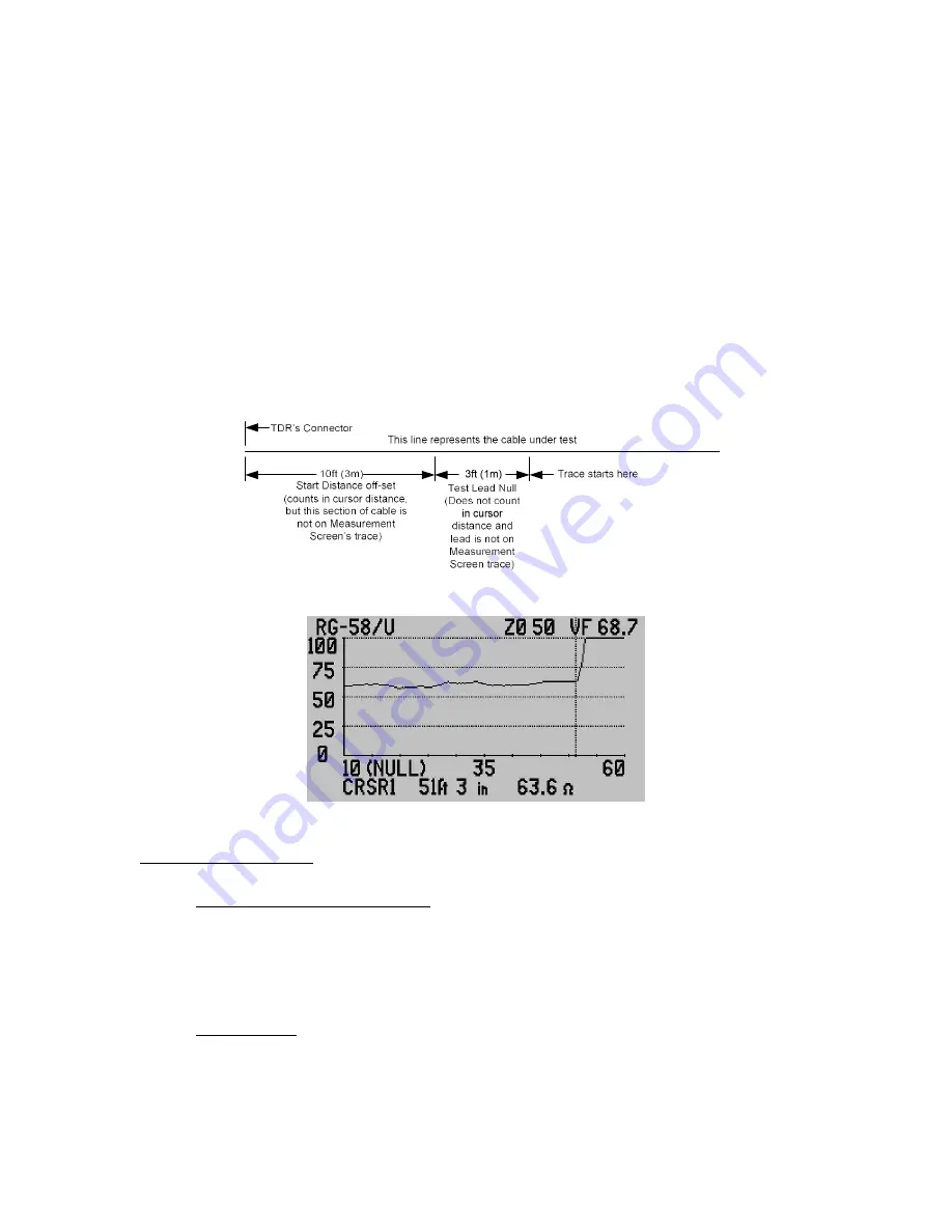
3. When Test Lead Null is on, the plot display will show the word (NULL) on the
left side of the range scale after the start distance. See figure 3-57. The cable
under test is a 51ft (15.5m) attached to a 7.5ft (2.3m) test lead that has been
removed from the trace using Test Lead Null. Also missing from the trace is the
first 10ft (3m) of the cable. However, the cursor marks the correct distance to the
end of the cable.
Figure 3-56
Figure 3-57
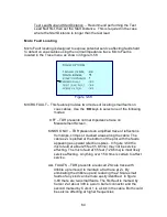
Test Lead Null Hints:
Pre-Stage the Measurement – Before entering Test Lead Null, set the
Range and Impedance Scale for the optimum view of the test lead in the
LCD plot. Example: for a 6ft (2m) 50 Ohms test lead, Set the Range to
10ft or 5 meters and the Z Scale to 100 Ohms. Then position Cursor 1 at
the end of the lead.
Short Leads – If a short test lead is used it may be difficult to see the open
end close to the TDR’s connector. Solution is to short the end of the test
lead to obtain a sharp downward turn at the test lead’s end, then mark the
end of the test lead.


