

49
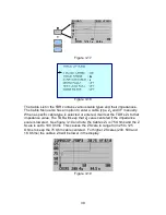
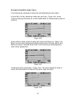
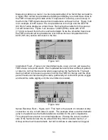
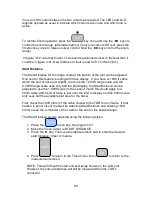
Figure 3-35
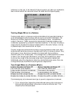
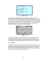
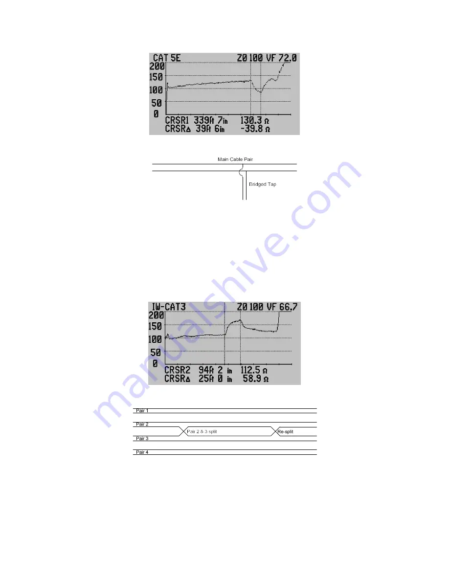
Figure 3-36
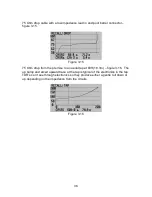
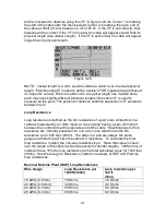
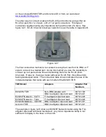
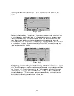
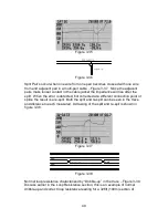
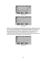
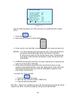
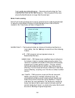
Split Pair’s occur when one wire from one pair becomes crossed with one wire
from and adjacent pair in a multi-pair cable – Figure 3-37. Since the adjacent
pairs make looser contact in the cable jacket the impedance will rise after the
split. When the error is detected, but corrected at a different connection point or
splice the result is a re-split. Both the split and re-split can be seen in the trace
and distance to each measured. A drawing of the split and re-spit is shown in
figure 3-38.
Figure 3-37
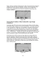
Figure 3-38
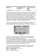
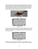
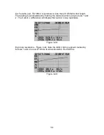
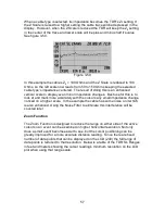
Normal loop resistance characterized by “Dribble-up” in the trace – Figure 3-39.
Discuss earlier in the Loop Resistance section, this is an example of normal
dribble-up and correct loop resistance reading for a 328ft (100m) section of


