
44
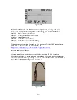
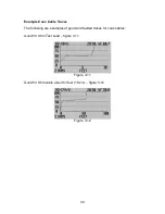
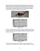
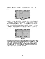
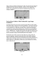
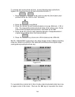
Whenever the Telco Test Leads or other alligator clip leads are connected, the
twist in the leads ends and the cable pair under test should remain as close as
possible as in figure 3-24. This reduces any impedance bumps to their minimum
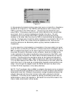
at the connection points as shown in figure 3-25. As the leads and cable pair’s
wires separate the impedance between them will climb rapidly and the display
will show a larger impedance bump at the connection point.
Figure 3-24
Figure 3-25
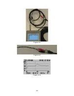
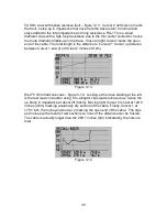
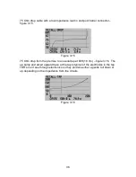
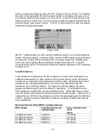
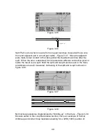
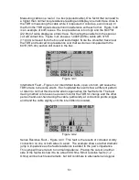
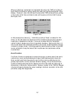
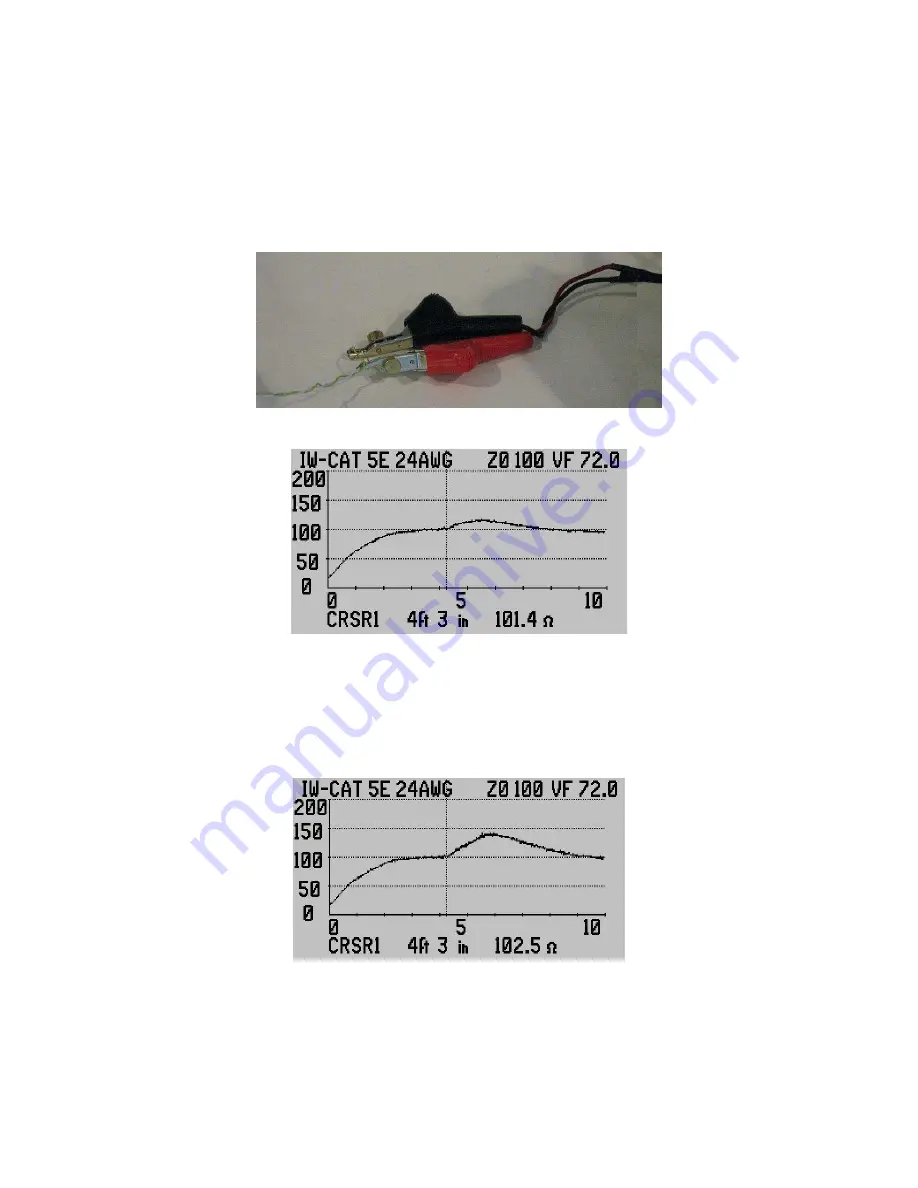
When a connection requires the clips and/or leads be separated be aware of this
increase in impedance at the connection point. Figure 3-26 shows the same telco
test lead connection’s trace, but with separation between the clips and 2 inches
(5cm) of wire un-twist.
Figure 3-26
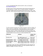
See AEA Technology’s application note AN222 Telco Style Alligator Clips for
more information about twisted pair connections. Application Notes are available


