Advanced Instruments 3900 Service Manual Download Page 58

4CP121 Rev0

(4C35/3905 Service Manual)

Page 2 of 4

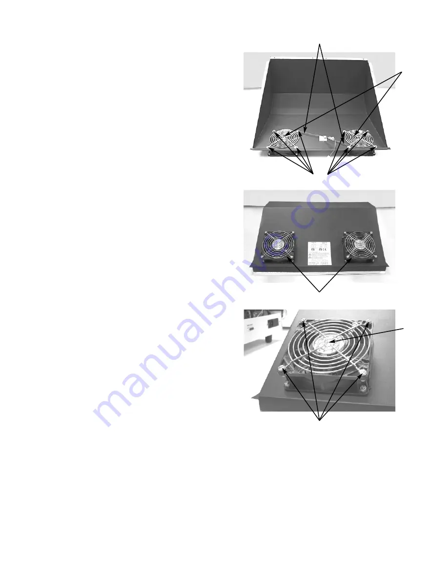
6.  Mount replacement fans with the flow

arrow pointing to the outside of the cover.
Orient the fans so that the wires (H) are
located as shown and align with the holes
provided on the cover.

7.  Reassemble the instrument by reversing

steps 1-5.

C

D

E

G

F

H

Summary of Contents for 3900

Page 1: ...3905SM Rev14 050415 The Advanced Osmometer Model 3900 Service Manual ...

Page 2: ......

Page 3: ...Printer 27 RS232 Serial Port Serial Loop Test 28 Yoke Clapper and Coil 28 Troubleshooting Table 29 5 Adjustments Insert Mode Position 39 Operating Head position 1 39 Head Up Down Sensor Board 40 Tube Gripper 40 6 Replacement Instructions Automatic Calibration Cassettes 4C3040 4CP042 Back Panel Upgrade 4C3008 4CP008 Block Probe 390340 39P340 Cassette Labels 4C3039 4CP039 Cassette Pusher Arm 390437 ...

Page 4: ...0 PCP520R Transistor Replacement PCB522 PCP522R Tube Gripper 4C3446 4CP446 Tube Sensors 390026 390028 25P048 Yoke Clapper and Coil 3LH230 3C2241 3D2404 3LP230 7 Schematics 4C3000 Interconnection Schematic 4C3450 Schematic 4C3450 Assembly Drawing PCB610 Schematic PCB610 Assembly Drawing APPENDICES A Symbol Definitions B Product Disposal and Recycling C Service Log Index The Advanced Model 3900 Serv...

Page 5: ...1 Introduction ...

Page 6: ......

Page 7: ...H2O per month Performance Over Operating Conditions Temperature Effects Less than 1 mOsm kg H2O for every 5 C 9 F ambient temperature change Operating Conditions Temperature Low Range 18 C to 35 C 64 F to 95 F High Range 18 C to 30 C 64 F to 86 F Room Humidity 5 to 80 relative humidity non condensing Storage Temperature 40 C to 45 C 40 F to 113 F Start up Time Actual time from power on to Osmomete...

Page 8: ...ee within the USA and Canada after normal business hours dial extension 2191 Call US 781 320 9000 elsewhere Or fax 781 320 0811 When calling Advanced Instruments have the model and serial number from the label on the back of the instrument and a description of the problem Use a telephone as close to the instrument as possible in order to facilitate making recommended diagnostic checks A service te...

Page 9: ...ce of a specific component that could be damaged by static electricity This symbol indicates the presence of alternating current AC This symbol indicates the presence of a fuse This symbol indicates the presence of protective earth ground This symbol indicates the power is ON This symbol indicates the power is OFF NOTE Additional symbol definitions are available in the Symbols section General Caut...

Page 10: ...s unplug the product from the electrical outlet and refer service to a qualified service technician The power cord extension cord power strip or power input module is damaged Liquid has been spilled into the interior of the product A foreign object has fallen into the product The product has been dropped or damaged by a falling object There are noticeable signs of overheating or a burning odor The...

Page 11: ...ifications made to this product that are not expressly approved in writing by the manufacturer will void the User authority to operate this product previously issued factory approvals and the User rights under the warranty The distributor or dealer may have applied additional local national or international approvals to this product Consult the distributor or dealer for more information and docume...

Page 12: ...B Electrical Equipment for Measurement Control and Laboratory Use EC Declaration of This product meets the intent of Conformity Low Directive 73 23 EEC the Low Voltage Voltage Directive Compliance was demonstrated using the following standards as listed in the Official Journal of the European Communities Consult the Declaration of Conformance certificate shipped with the product if required for th...

Page 13: ...2 General Overview ...

Page 14: ......

Page 15: ...The Advanced Model 3900 Service Manual 15 Circuit Diagram ...

Page 16: ...roprocessor runs the software stored in the EPROM and uses the battery backed up 8 Kbyte static RAM to store information A D Converters Two dual slope A D converters using programmable timer modules provide interface from the sample and block probes to the microprocessor The A D converters use a reference voltage of 6 25 VDC and provide 15 bits 1 4 ohm of resolution Sample Cooling Interface The th...

Page 17: ...net is placed in the correct position for the ID label on the cassette The sensors all work the same way the output leads are open normally and when a magnetic field of sufficient strength passes near the sensor the leads are closed shorted The magnetic sensors are interfaced to the microprocessor through a peripheral interface adapter Cassette Stat Tube Detectors Both tube detectors use a reflect...

Page 18: ... position of the sample head at the cassette tube retrieval placement position The controlling system consists of an optical switch adjustable and a slotted disk The optical switch is interfaced to the microprocessor through a peripheral interface adapter The head rotation travel is controlled by two mechanical limit switches one is located on the right side and one on the left side The limit swit...

Page 19: ...Operator Supervisor Keys 3D3185 Power Cord specify voltage and country Stir Freeze Wire 3C2243 Probe Stir Alignment Kit 3LA700 Serial Port Computer Cable with DB9S 3 Meter Shielded RS 232 330053 6 Meter Shielded RS 232 330056 9 Meter Shielded RS 232 330059 Barcode Reader with Stand 390016 Service Manual 3905SM User s Guide 3905 How to order To order parts supplies and accessories contact the Advan...

Page 20: ...20 The Advanced Model 3900 Service Manual Notes ...

Page 21: ...3 Maintenance ...

Page 22: ......

Page 23: ... of tubing supplied with the 3900 to the reservoir drain port in the back panel of the instrument 2 Place a container under the tubing to catch the draining heat transfer fluid 3 Press and hold in the reservoir pump pushbutton for a few moments to pump the heat transfer fluid remaining in the system out into the container under the reservoir drain tubing 4 Disconnect the quick connector and dispos...

Page 24: ...off the instrument if desired 3 Do not cover the instrument unless it is turned off One week or longer 1 Rinse the probe clean with distilled water and wipe it dry 2 Turn off the instrument 3 Unplug the power cord from the wall outlet The Advanced Model 3900 Service Manual Storage and Shutdown ...

Page 25: ...4 Troubleshooting ...

Page 26: ......

Page 27: ...nnecting an ohmmeter across the motor leads The resistance across the black and yellow red and white yellow and green white and blue leads should be between 19 20 ohms The resistance across the black and green red and blue leads should be 38 40 ohms Pusher Arm Motor The motor windings of this motor can be checked by connecting an ohmmeter across the motor leads The resistance across the black and ...

Page 28: ...stem wiring or change the voltage selection on the printer PCB JP1 to VCC RS232 Serial Port Serial Loop Test This Test Menu item does not function properly To test the RS 232 serial port follow the instructions for an RS 232 Setup in Appendix E in the User s Guide and then perform the Display Print Test to determine if the instrument is communicating properly over the RS 232 serial port Test chara...

Page 29: ... correct arrowheads matching If the fuses were blown and the replacement fuses blow also contact Advanced Instruments for Hot Line Technical Service Abrupt loss of power no display Block Probe Failure Switch the instrument off then on Check the sample probe by running the A D Test If the error message persists contact Advanced Instruments for Hot Line Technical Service Block Probe Open Switch the ...

Page 30: ...ror message persists contact Advanced Instruments for Hot Line Technical Service Full Deck Check whether further testing is being impeded by too many tested cassettes remaining in the right output cassette deck Sensor is located in front left side of the output tray a Remove some of the tested cassettes from the right cassette deck especially the front b At Press START to Continue press START to r...

Page 31: ...chnical Service Insufficient Data Check that your request for recall results match the number of runs completed Re enter recall with fewer runs No Barcodes for This Cassette Cassette If an unscanned cassette is introduced during a scanned batch run the cassette will be tested and the results recorded without batch identification Try to avoid introducing unscanned cassettes during batch test runs N...

Page 32: ...ter successful recalibration contact Advanced Instruments for Hot Line Technical Service Reset Probe Configuration displayed during the power up sequence If not followed by Select Test Item contact Advanced Instruments for Hot Line Technical Service If followed by Select Test Item see Symptom item Thermoelectrics Driver Failure Reset Probe Configuration displayed during the power up sequence follo...

Page 33: ...ecessary to avoid generating bubbles before the freeze buzz occurs 4 The 3900 is not designed to test thick or very viscous samples 5 Check correct the probe bin numbers Test another aliquot of that sample in a clean sample tube Sample Did Not Freeze Poor or no freeze buzz 1 Check for debris in the magnetic gap between the clapper and coil see User Guide Figure 7 2 The stir freeze wire must be fir...

Page 34: ...lacement of the yoke clapper and coil by a qualified service technician Sample Probe Failure Switch the instrument off then on Check the sample probe by running the A D Test If the error message does not persist and other messages are not displayed ignore this message Replace the sample probe Sample Probe Open Switch the instrument off then on Check the sample probe by running the A D Test If the ...

Page 35: ...r messages are not displayed ignore this message Replace the sample probe WARNING Sample Count Incorrect Produced by a recall operation or at the completion of a batch barcode run if samples recorded does not match that entered for batch barcode run 1 Check original printout for entered vs run 2 If test errors occurred these may not have been recorded as valid tests resulting in the message 3 If t...

Page 36: ...36 The Advanced Model 3900 Service Manual Notes ...

Page 37: ...5 Adjustments ...

Page 38: ......

Page 39: ...select YES for Insert Test Check the alignment of the operating head in the insert well Note the direction and the amount of misalignment if any 2 Remove the back cover from the instrument 3 Manually rotate the head to probe wipe position and slightly loosen the cap screw A on the anti rotation block 4 Manually rotate the operating head over the cooling well using the position over the well as a r...

Page 40: ...the sample head nests at the bottom of the V with the sample head fully down Tighten the screws and then check the position by cycling the head 12 Reattach the back cover to the instrument NOTE The back cover should not remain off for extended periods of time 1 hour while samples are being tested Excessive heat buildup inside the unit will occur Head Up Down Sensor Board 1 Remove the back cover sc...

Page 41: ...6 Replacement Instructions ...

Page 42: ......

Page 43: ...el 3900 will identify the automatic calibration cassette and initiate the calibration sequence 4 If the results are within the acceptable range the Model 3900 will be automatically recalibrated and the message Calibration Complete will be displayed 5 Return the Supervisor Operator keyswitch to operator mode if desired Model 4C3 1 Position the Supervisor Operator keyswitch in the supervisor positio...

Page 44: ......

Page 45: ... to gain access to the two wire back cover fan connector 4 Unplug the connector to disconnect the fans Pull the cover off gently CAUTION Do not attempt to remove the cover from the unit until the fan is disconnected 5 Plug in the fan to the new back panel connector A 6 Use the eight screws B removed in step 2 to attach the new back panel For additional information or technical assistance please co...

Page 46: ......

Page 47: ... the power cord 2 Remove all eight screws A from the back cover of the instrument Lift the cover back gently and then down to gain access to the two wire back cover fan connector B Unplug the connector to disconnect the fans Pull the cover off gently and place it on a level surface CAUTION Do not attempt to remove the cover from the unit until the fan is disconnected 3 From the back of the unit re...

Page 48: ...remove all cable ties attached to the block probe cable 7 Remove the block probe cable from the cooling assembly 8 Insert thermal grease into the block probe hole and insert the probe end of the new cable into the hole until it will not go any further Insert slowly so that the probe is not damaged allowing the thermal grease to be displaced by the probe 9 Note the block bin number located on the b...

Page 49: ...ition of the magnet s on the underside of the cassette Then look at the illustration to identify the position number s Compare the position with the decoding chart For example if a cassette has magnets in positions 2 and 4 there will be a yes in the columns for Position 2 and Position 4 and a no in the other columns In the last column Cassette No there will be a 10 Before applying the new label cl...

Page 50: ......

Page 51: ...ment and disconnect the power cord 2 Remove all eight screws A from the back cover of the instrument Lift the cover back gently and then down to gain access to the two wire back cover fan connector B Unplug the connector to disconnect the fans Pull the cover off gently and place it on a level surface CAUTION Do not attempt to remove the cover from the unit until the fan is disconnected 3 Open the ...

Page 52: ...t with the switch 8 Install the replacement pusher arm with the hardware that was previously removed 9 Adjust the arm so that the bottom edge is parallel with the deck 10 Check for proper alignment by cycling a cassette in the tube transport test mode The arm is adjusted correctly when the cassette is pushed into the proper position for indexing and indexes properly even when the cassette is initi...

Page 53: ...screw and stop nut I 12 Once it has been determined that the pusher arm and foam bracket assemblies are properly adjusted and all other installations are complete install the front panel rear cover and restore power to the instrument 39P437 Rev0 4C35 3905 Service Manual Page 3 of 3 E I H I G F ...

Page 54: ......

Page 55: ...rument and disconnect the power cord 2 Remove all eight screws A from the back cover of the instrument Lift the cover back gently and then down to gain access to the two wire back cover fan connector B Unplug the connector to disconnect the fans Pull the cover off gently and place it on a level surface CAUTION Do not attempt to remove the cover from the unit until the fan is disconnected 3 Loosen ...

Page 56: ...o the replacement motor housing as far as they will go 8 Install the four standoffs F onto setscrews and tighten 9 Reverse steps 3 4 making sure the coupler is equally spaced between the motor shaft and the lead screw Apply Loctite 271 or equivalent to setscrews C in the drive coupling prior to assembly 4CP420 Rev0 4C35 3905 Service Manual Page 2 of 2 C D G H F E ...

Page 57: ...ord 2 Remove all eight screws A from the back cover of the instrument Lift the cover back gently and then down to gain access to the two wire back cover fan connector B Unplug the connector to disconnect the fans Pull the cover off gently and place it on a level surface CAUTION Do not attempt to remove the cover from the unit until the fan is disconnected 3 From the inside of the back cover remove...

Page 58: ... 6 Mount replacement fans with the flow arrow pointing to the outside of the cover Orient the fans so that the wires H are located as shown and align with the holes provided on the cover 7 Reassemble the instrument by reversing steps 1 5 C D E G F H ...

Page 59: ...s disconnected 3 Remove the shroud I beneath the cooling assembly by removing the butterfly nut J and removing each half separately 4 Disconnect the fan connector K from the harness 5 Using a short 3 screwdriver or right angle screwdriver remove the set of four mounting screws L on the fan 6 Reverse steps 1 5 to install the replacement fan with the flow arrow pointing upward NOTE Self tapping scre...

Page 60: ...e all mounting screws N from the front panel of the instrument and pull the panel down and out 4 Disconnect the fan connector O from the harness 5 Remove the four socket cap screws and associated hardware P only two of the four screws are pictured 6 Remove the fan Q from the instrument 7 Install the replacement fan with the air flow arrow pointing away from the cooling reservoir R 8 Reverse steps ...

Page 61: ...front sample door A and pull the sides out gently to remove front sample door 2 Remove all mounting screws B from the front panel of the instrument and pull the panel down and out 3 Drain the heat transfer fluid as instructed in the User s Guide Maintenance section 4 Turn off the instrument and disconnect the power cord 5 Disconnect the wires C attached to the pump D noting that the red yellow wir...

Page 62: ... Attach the pump fittings to appropriate hoses The top fitting connects to the hose going to the sample cooling well The bottom fitting connects to the cooling reservoir hose Cover all exposed areas with refrigeration tape 11 Secure the pump to the unit with mounting screws E 12 Reverse steps 1 3 Check proper flow in the cooling well before securing the front cover E F ...

Page 63: ...e human body or other conductor may damage system boards or static sensitive devices NEVER UNPACK TOUCH OR HANDLE ANY PCB WITHOUT WEARING A GROUNDING EARTHING STRAP TO MINIMIZE YOUR STATIC DISCHARGE Instruction for Deck Removal 1 Drain the heat transfer fluid as instructed in the instrument s User Guide 2 Turn off the instrument and disconnect the power cord 3 Remove all eight screws A from the ba...

Page 64: ... heat transfer fluid fill port fitting F 8 From the back of the unit disconnect the main power harness connector PS1 9 Disconnect the communications port ribbon cable connector from J5 on the motor control board G 10 Disconnect the four connectors J3 J8 J12 and J13 from the Main Control PCB H to the front panel harness assembly Disconnect the printer power connectors SP12 11 Disconnect the cooling...

Page 65: ...4CP310 Rev0 4C35 3905 Service Manual Page 3 of 5 G H J1 J2 J9 J7 J8 J1 J2 J3 G H J1 J2 J3 J5 J6 PSI J12 J3 J11 J13 ...

Page 66: ...sample cooling thermoelectric connectors TJ1 and TP1 K 15 Remove the three slotted screws L holding the cooling assembly in place and allow the cooling assembly to rest on the bottom of the base assembly NOTE Make note of the align ment position of the cooling well in the deck prior to removal 15 Disconnect the drain tubing from the base assembly 17 Carefully pull the deck out through the back of ...

Page 67: ...es O from the tank 4 Disconnect the four thermoelectric connectors P from the main harness 5 Disconnect the reservoir thermistor Q from the PC Board 6 Remove the two screws R from the fan and mounting bracket and slide the bracket away from the cooling reservoir 7 Remove the four screws S holding the reservoir in place 8 Install the replacement reservoir noting correct orientation outlet hose to p...

Page 68: ......

Page 69: ...th the human body or other conductor may damage system boards or static sensitive devices NEVER UNPACK TOUCH OR HANDLE ANY PCB WITHOUT WEARING A GROUNDING EARTHING STRAP TO MINIMIZE YOUR STATIC DISCHARGE Instruction for Deck Removal 1 Drain the heat transfer fluid as instructed in the instrument s User Guide 2 Turn off the instrument and disconnect the power cord 3 Remove all eight screws A from t...

Page 70: ... heat transfer fluid fill port fitting F 8 From the back of the unit disconnect the main power harness connector PS1 9 Disconnect the communications port ribbon cable connector from J5 on the motor control board G 10 Disconnect the four connectors J3 J8 J12 and J13 from the Main Control PCB H to the front panel harness assembly Disconnect the printer power connectors SP12 11 Disconnect the cooling...

Page 71: ...4CP391 Rev1 4C35 3905 Service Manual Page 3 of 5 G H J1 J2 J9 J7 J8 J1 J2 J3 G H J1 J2 J3 J5 J6 PSI J12 J3 J11 J13 ...

Page 72: ...sample cooling thermoelectric connectors TJ1 and TP1 K 15 Remove the three slotted screws L holding the cooling assembly in place and allow the cooling assembly to rest on the bottom of the base assembly NOTE Make note of the align ment position of the cooling well in the deck prior to removal 15 Disconnect the drain tubing from the base assembly 17 Carefully pull the deck out through the back of ...

Page 73: ...es O from the tank 4 Disconnect the four thermoelectric connectors P from the main harness 5 Disconnect the reservoir thermistor Q from the PC Board 6 Remove the two screws R from the fan and mounting bracket and slide the bracket away from the cooling reservoir 7 Remove the four screws S holding the reservoir in place 8 Install the replacement reservoir noting correct orientation outlet hose to p...

Page 74: ......

Page 75: ...sconnect the power cord 2 Remove all eight screws A from the back cover of the instrument Lift the cover back gently and then down to gain access to the two wire back cover fan connector B Unplug the connector to disconnect the fans Pull the cover off gently and place it on a level surface CAUTION Do not attempt to remove the cover from the unit until the fan is disconnected 3 Remove the two screw...

Page 76: ... 2 Thread the sensor adjustment screw H through the front of the sensor mounting and position the sensor approximately where it was before removal marked position 3 Position the sensor in place over the disk K and in the mounting block secure with the two screws C 4 Connect the sensor to the main harness 5 Run HEAD ROTATION and or TUBE TRANSPORT tests from the test menu to check adjust the sensor ...

Page 77: ...edium flat bladed screwdriver Warning Hazardous Voltage CAUTION A discharge of static electricity from contact with the human body or other conductor may damage system boards or static sensitive devices NEVER UNPACK TOUCH OR HANDLE ANY PCB WITHOUT WEARING A GROUNDING EARTHING STRAP TO MINIMIZE YOUR STATIC DISCHARGE CAUTION Improper connections may cause damage to the instrument CAUTION The instrum...

Page 78: ... them in place You may need to bend the locking tab on the crimp back up slightly NOTE The current connector has 13 pin slots of which slots 1 through 12 are used The replace ment connector has 14 slots and will use slots 3 through 14 The wires however must remain in the same order 5 Remove the old display by removing the four screws E that attach it to instrument Save the screws for the new displ...

Page 79: ...ently and then down to gain access to the two wire back cover fan connector B Unplug the connector to disconnect the fans Pull the cover off gently and place it on a level surface CAUTION Do not attempt to remove the cover from the unit until the fan is disconnected 3 Position the sample drip return C with the drip flange inside the well opening on the deck Loosen the retaining hardware D and slid...

Page 80: ...and the tube gripper Angle the drip return well so that the path of the tube travel is directly over the drip return well channel and wiper 7 Securely tighten the two nuts 8 Operate the unit in the normal operating mode to insure that the return well is aligned properly NOTE The drip return well is aligned when there is no evidence of interference with the tube gripper when a sample is placed in t...

Page 81: ...mounting screws B from the front panel of the instrument and pull the panel down and out 5 Check the data label on the body of the heat transfer fluid pump Make sure that the manufacturer is KNF Fluids and that the listed type is PML4313 NF30 If it is continue with step 6 Please note caution below For additional information or technical assistance please contact Advanced Instruments Hot Line Servi...

Page 82: ...o unscrew it Remove the diaphragm from the pump taking care not to lose the small washers b Transfer the small washers from the threaded stud on the old diaphragm to the new one and then screw the new diaphragm into the pump firmly by hand c Press the edge of the new diaphragm down firmly into place 8 Change the valve plates G a Take the rear half of the pump head set aside earlier and remove the ...

Page 83: ...steps 3 4 11 Return the heat tranfer fluid drained in step 1 through the front fill port per the instructions contained in the User Guide 12 Plug in the instrument and turn on the power The instrument will run a self diagnostics program including a heat transfer fluid level check 13 Run a few test samples of calibration standards to check proper instrument operation 4CP190 Rev1 4C35 3905 Service M...

Page 84: ......

Page 85: ...ds or static sensitive devices NEVER UNPACK TOUCH OR HANDLE ANY PCB WITHOUT WEARING A GROUNDING EARTHING STRAP TO MINIMIZE YOUR STATIC DISCHARGE Instruction 1 Drain the heat transfer fluid as instructed in the instrument s User Guide 2 Turn off the instrument and disconnect the power cord 3 Remove all eight screws A from the back cover of the instrument Lift the cover back gently and then down to ...

Page 86: ...move the original 5 32 tubing lengths from the reservoir tank and drain hose 8 Cut a 6 length of tubing off from the 11 length supplied with the upgrade kit Tubing should be attached prior to installing the pump 9 Using the original pump mounting holes E install the new pump bracket to the base with the open end away from the cooling system reservoir The pump should be mounted to the bracket prior...

Page 87: ...where MP1 MP2 CP8 CP7 and CP9 cables protrude from the 4C3150 harness assembly Twist excess braid together and seal with a hot soldering iron I Repeat for braided section where CP12 protrudes on the 4C3524 harness assembly 14 Gather the 4C3150 4C3525 harness and reservoir tank thermistor cable assembly together and combine using an EZ twist lock tie J 15 Gather the 4C3485 harness assembly and the ...

Page 88: ...ess assembly to each mount with a tie wrap Q 22 Apply a small adhesive backed mount to the thermal printer mechanism base Using a short tie wrap secure the thermal printer mechanism data cable to the mount R 23 Using small tie wraps secure the 4C3525 cable harness to the two forward standoffs of the printer control PCB mounting bracket S 24 Ensure enough cable is extended beyond the standoff to al...

Page 89: ...AP TO MINIMIZE YOUR STATIC DISCHARGE Instruction for Deck Removal 1 Turn off the instrument and disconnect the power cord 2 Remove all eight screws A from the back cover of the instrument Lift the cover back gently and then down to gain access to the two wire back cover fan connector B Unplug the connector to disconnect the fans Pull the cover off gently and place it on a level surface CAUTION Do ...

Page 90: ...nector PS1 8 Disconnect the communications port ribbon cable connector from J5 on the motor control board G 9 Disconnect the four connectors J3 J8 J12 and J13 from the Main Control PCB H to the front panel harness assembly Disconnect the printer power connectors SP12 10 Disconnect the cooling tank thermistor connector from J6 on the motor control board and clip all cable ties to remove the cable c...

Page 91: ...4CP440 Rev0 4C35 3905 Service Manual Page 3 of 6 G H J1 J2 J9 J7 J8 J1 J2 J3 G H J1 J2 J3 J5 J6 PSI J12 J3 J11 J13 ...

Page 92: ...4 Remove the three slotted screws L holding the cooling assembly in place and allow the cooling assembly to rest on the bottom of the base assembly NOTE Make note of the align ment position of the cooling well in the deck prior to removal 15 Disconnect the drain tubing from the base assembly 16 Carefully pull the deck out through the back of the instrument 17 Place the deck inverted on a stable st...

Page 93: ...n idler gear by removing the stop nut and bushings R 6 Remove the top gear plate to reveal two slotted screws S Remove these screws to disassemble the remaining components 7 The top section of the assembly can be accessed by removing the three slotted screws T from the rotation cap NOTE Lubricating grease part MSC003 is also required on the surface areas top and bottom of the rotation mount that m...

Page 94: ...he pins into the unthreaded holes of the rotation mount 11 Reassemble the remaining components by reversing steps 1 7 NOTE Position 1 will require adjustment and the head up down sensor will need to be checked Refer to the appropriate adjustment procedures in the Adjustments section of this manual ...

Page 95: ... A discharge of static electricity from contact with the human body or other conductor may damage system boards or static sensitive devices NEVER UNPACK TOUCH OR HANDLE ANY PCB WITHOUT WEARING A GROUNDING EARTHING STRAP TO MINIMIZE YOUR STATIC DISCHARGE Instruction for Deck Removal 1 Turn off the instrument and disconnect the power cord 2 Remove all eight screws A from the back cover of the instru...

Page 96: ...nector PS1 8 Disconnect the communications port ribbon cable connector from J5 on the motor control board G 9 Disconnect the four connectors J3 J8 J12 and J13 from the Main Control PCB H to the front panel harness assembly Disconnect the printer power connectors SP12 10 Disconnect the cooling tank thermistor connector from J6 on the motor control board and clip all cable ties to remove the cable c...

Page 97: ...4CP416 Rev0 4C35 3905 Service Manual Page 3 of 5 G H J1 J2 J9 J7 J8 J1 J2 J3 G H J1 J2 J3 J5 J6 PSI J12 J3 J11 J13 ...

Page 98: ...14 Remove the three slotted screws L holding the cooling assembly in place and allow the cooling assembly to rest on the bottom of the base assembly NOTE Make note of the alignment position of the cooling well in the deck prior to removal 15 Disconnect the drain tubing from the base assembly 16 Carefully pull the deck out through the back of the instrument 17 Place the deck inverted on a stable st...

Page 99: ...rew and then from the top of the deck back off the idler gear screw so that the gear and bushings N can be removed from the deck 2 Note the orientation of the center bearing on the gear and the condition of the bushings Replace if they appear to be excessively worn 3 Install the gear by reversing steps 1 2 NOTE The stop nut should be tightened only until the bushings cannot rotate freely M N ...

Page 100: ......

Page 101: ...R UNPACK TOUCH OR HANDLE ANY PCB WITHOUT WEARING A GROUNDING EARTHING STRAP TO MINIMIZE YOUR STATIC DISCHARGE Instruction for Deck Removal 1 Turn off the instrument and disconnect the power cord 2 Remove all eight screws A from the back cover of the instrument Lift the cover back gently and then down to gain access to the two wire back cover fan connector B Unplug the connector to disconnect the f...

Page 102: ...o place 11 Unplug the head up down motor cable connection and remove the spiral wrap 12 Plug the new head up down motor cable connector into the existing motor connector 13 Fold or loop the excess existing motor connector leads so that they cannot interfere with the movement of the operating head and secure the leads and connector firmly to the motor with the long cable tie supplied 4CP965 Rev1 4C...

Page 103: ...ithout allowing the cable to bind in the sensor flag power supply heat sinks or any other component 24 Leave the operating head in the position with the probe centered between the probe wipers for protection 25 Temporarily reconnect the power cord turn on the instrument power and check for proper operation of the instrument before finally closing the back cover CAUTION During this check be extreme...

Page 104: ......

Page 105: ...ruction 1 Drain and save the heat transfer fluid as instructed in the instrument User Guide 2 Turn off the instrument and disconnect the power cord 3 Open the front sample door A and pull the sides out gently to remove the front sample door 4 Remove all mounting screws B from the front panel of the instrument and pull the panel down and out 5 The easiest way to replace the old pump is to remove it...

Page 106: ...ctioning reconnect the power cord and turn on the instrument CAUTION During this check be extremely careful to avoid contact with the electrical components inside the instrument The instrument will recognize that the heat transfer fluid has been removed and prompt G F you to add fluid Add heat transfer fluid as described in your instrument s User Guide 15 After adding fluid use the reservoir pump ...

Page 107: ...rews A from the back cover of the instrument Lift the cover back gently and then down to gain access to the two wire back cover fan connector B Unplug the connector to disconnect the fans Pull the cover off gently and place it on a level surface CAUTION Do not attempt to remove the cover from the unit until the fan is disconnected 3 Disconnect the ribbon cable C from the main harness D 4 Remove th...

Page 108: ...2 NOTE Before pressing the keypad firmly into place check the alignment of the display window and the keypad with the display panel 8 Run the keypad test see User Guide Calibration section to verify that the keypad is functioning properly C D E F G ...

Page 109: ... to disconnect the fans Pull the cover off gently and place it on a level surface CAUTION Do not attempt to remove the cover from the unit until the fan is disconnected 3 Manually move the operating head so that the probe is located over the cooling well C 4 Remove the pivot pin D and the pivot plate E 5 Pull the tube gripper F down and off of the mandrel 6 Remove the coil spring G 7 Disconnect th...

Page 110: ...et screw K and pulling the probe up through the mandrel 11 Install the probe in the replacement mandrel making sure that the probe is aligned properly in the mandrel using the probe alignment tool See the instrument s user guide Calibration section 12 See the Tube Gripper Adjustment section for proper adjustment of the probe and mandrel assembly on the sample handler 13 Reverse steps 1 8 to comple...

Page 111: ...t Instruction 1 Turn off the instrument and disconnect the power cord 2 Remove all eight screws A from the back cover of the instrument Lift the cover back gently and then down to gain access to the two wire back cover fan connector B Unplug the connector to disconnect the fans Pull the cover off gently and place it on a level surface CAUTION Do not attempt to remove the cover from the unit until ...

Page 112: ... the upper section of the PCB bracket Two holes in the motor control PCB mount into the standoffs 5 Remove both boards from the deck 6 Either board can be replaced separately they do not need to be a matched pair The boards can be separated by removing the three slotted screws and associated hardware NOTE When reassembling make sure that connector J4 near the bottom of the motor control PCB mates ...

Page 113: ...4CP450 Rev1 4C35 3905 Service Manual Page 3 of 3 E J12 J3 J11 J13 ...

Page 114: ......

Page 115: ...ng the instrument cover shut off the power switch and disconnect the power cord to help avoid exposure to dangerous voltages particularly around the fuses power switch and power supply CAUTION Improper connections may cause damage to the instrument Instruction 1 Turn off the instrument and disconnect the power cord 2 Remove all eight screws A from the back cover of the instrument Lift the cover ba...

Page 116: ...terminal and the violet wires to the terminal C D E F 6 Disconnect the three wires from the power supply input terminals NOTE The green yellow wire is connected to the ground terminal and the solid blue and brown wires to the N and L terminals respectively CAUTION Note that the position of the terminals depends upon the manufacturer of the power supply 7 From underneath the instrument remove the t...

Page 117: ...minal Attach the violet wires to the lower terminal Take care to pull the connections away from each other when you tighten the screws to reduce the chance of an output short 5 Remove the three input screws from the input terminals at the rear of the instrument 6 Attach the green yellow wire to the lower terminal 7 Attach the brown wire to the center terminal 8 Attach the blue wire to the upper te...

Page 118: ......

Page 119: ...ischarge of static electricity from contact with the human body or other conductor may damage system boards or static sensitive devices NEVER UNPACK TOUCH OR HANDLE ANY PCB WITHOUT WEARING A GROUNDING EARTHING STRAP TO MINIMIZE YOUR STATIC DISCHARGE Instruction 1 Turn off the instrument and disconnect the power cord 2 Remove all eight screws A from the back cover of the instrument Lift the cover b...

Page 120: ...res D from the printer PCB assembly 4 Remove the four nuts and associated hardware E that hold the print head bracket to the print head door 5 Remove the three retaining screws that hold the print head to the bracket 6 Remove the old print head and install the new one by reversing steps 1 5 C D E E C D ...

Page 121: ...ic sensitive Observe all necessary ESD precautions A discharge of static electricity from contact with the human body or other conductor may damage system boards or static sensitive devices NEVER UNPACK TOUCH OR HANDLE ANY PCB WITHOUT WEARING A GROUNDING EARTHING STRAP TO MINIMIZE YOUR STATIC DISCHARGE Instruction 1 Turn off the instrument and disconnect the power cord 2 Remove all eight screws A ...

Page 122: ...he fan is disconnected 3 Disconnect the ribbon cable C and power cable 5 wires D from the printer PCB assembly and remove the connectors E attached to the main harness from the PCB assembly 4 Remove the four retaining screws and associated hardware 5 Install the replacement PCB by reversing steps 1 4 C E F C E D D ...

Page 123: ...C DISCHARGE Instruction 1 Turn off the instrument and disconnect the power cord 2 Remove all eight screws A from the back cover of the instrument Lift the cover back gently and then down to gain access to the two wire back cover fan connector B Unplug the connector to disconnect the fans Pull the cover off gently and place it on a level surface CAUTION Do not attempt to remove the cover from the u...

Page 124: ...h tie wrap to secure this connection against the harness 7 Locate the new 390117 printer power harness provided in the kit and connect the brown three pin connector to J1 G on the printer board 8 Locate and disconnect the fan power connection H at the sample well assembly 9 Connect the T shaped end I of 390117 between the sample well fan and its harness 10 Using tie wraps and the adhesive mounts p...

Page 125: ...s shown in the drawings below Note For 4250 or 4D3 cryoscopes the alignment tool must be rotated 90º from its position with osmometers 2 Align the probe as follows If aligning a metal probe bend the metal probe stem gently by hand as necessary to align the probe along the RAISED V CENTERLINE of the probe alignment tool If aligning a non metallic probe rotate the probe so that any curvature in the ...

Page 126: ...nd reset the stir freeze wire c Firmly retighten the stir freeze wire setscrew s As necessary bend the wire so that its tip is directly over the STEP d Replace the head cover The following instructions refer to the 4250 or 4D3 cryoscope The bottom of the stir freeze wire should be even with alignment tool LEVEL A a Remove the head cover b Loosen the stir freeze wire setscrew s and reset the stir f...

Page 127: ...itive devices NEVER UNPACK TOUCH OR HANDLE ANY PCB WITHOUT WEARING A GROUNDING EARTHING STRAP TO MINIMIZE YOUR STATIC DISCHARGE Instruction 1 Drain the heat transfer fluid as instructed in the instrument s User Guide 2 Turn off the instrument and disconnect the power cord 3 Remove all eight screws A from the back cover of the instrument Lift the cover back gently and then down to gain access to th...

Page 128: ...inserting the applicator into the cavity as far as possible before applying force to the plunger Slowly back the applicator out of the opening while dispensing thermal compound to ensure the cavity is properly filled 11 Insert the replacement reservoir tank thermistor probe into the thermal compound filled reservoir tank probe opening as far as possible While keeping inward pressure on the reservo...

Page 129: ...oir tank is currently not at operating temperature approximately 12 C After a 30 minute interval the LED should be illuminated indicating that the tank has reached operating temperature During operation the LED may extinguish from time to time as the reservoir tank temperature cycles 16 Turn off the instrument power reconnect the rear cover cooling fans and reattach both front and rear covers and ...

Page 130: ......

Page 131: ... the instrument and disconnect the power cord 2 Remove all eight screws A from the back cover of the instrument Lift the cover back gently and then down to gain access to the two wire back cover fan connector B Unplug the connector to disconnect the fans Pull the cover off gently and place it on a level surface CAUTION Do not attempt to remove the cover from the unit until the fan is disconnected ...

Page 132: ...es attached to the block probe cable 7 Support the bottom of the cooling assembly while removing the three retaining screws from the top of the deck J 8 Remove the cooling assembly from the rear of the instrument 9 Install the new cooling assembly by reversing steps 1 7 Check for proper alignment of the sample cooling assembly by operating the unit in the head rotation insert mode test before secu...

Page 133: ...r cord 2 Remove all eight screws A from the back cover of the instrument Lift the cover back gently and then down to gain access to the two wire back cover fan connector B Unplug the connector to disconnect the fans Pull the cover off gently and place it on a level surface CAUTION Do not attempt to remove the cover from the unit until the fan is disconnected 3 Locate and unplug the sample probe co...

Page 134: ...ter hole in the mandrel not the large D shaped hole 8 Temporarily tighten the probe setscrew slightly just enough to keep the probe from falling out of the mandrel 9 Replace the tube gripper pivot plate and pivot plate pin 10 Reconnect the probe connector to the mating connector on the head chassis taking care once again not to touch or bend the connecting pins 11 Arrange the leads so that they wi...

Page 135: ...ary 4 a If aligning a metal probe bend the metal probe stem gently by hand as necessary to align the probe along the RAISED V CENTERLINE of the probe alignment tool b If aligning a non metalic probe rotate the probe so that any curvature in the probe is in the back to front direction parallel to the stir wire action 5 The bottom of the stir freeze wire should be even with alignment tool LEVEL B th...

Page 136: ...e probe bead must also be axially centered in the sample If horizontal adjustment is necessary bend the metal probe stem gently by hand in the required direction to align it with the raised V centerline on the footed face of the alignment tool Recheck and readjust the bead position as necessary 5 The bottom of the stir freeze wire should be even with alignment tool STEP or up to 1 32 or 1 mm highe...

Page 137: ...n the Service Log at the end of the user s guide then press the STOP soft key The display will change to Probe Bin Test 10 Press SETUP to enter the SETUP menu then repeatedly press the soft key until the display reads Set Sample Bin 11 At Set Sample Bin press the START soft key The display will report the current sample bin number setting 12 If the current sample bin number setting is not the same...

Page 138: ......

Page 139: ...proper connections may cause damage to the instrument CAUTION A discharge of static electricity from contact with the human body or other conductor may damage system boards or static sensitive devices NEVER UNPACK TOUCH OR HANDLE ANY PCB WITHOUT WEARING A GROUNDING EARTHING STRAP TO MINIMIZE YOUR STATIC DISCHARGE Instruction for Deck Removal 1 Turn off the instrument and disconnect the power cord ...

Page 140: ...e heat transfer fluid fill port fitting F 7 From the back of the unit disconnect the main power harness connector PS1 8 Disconnect the communications port ribbon cable connector from J5 on the motor control board G 9 Disconnect the four connectors J3 J8 J12 and J13 from the Main Control PCB H to the front panel harness assembly Disconnect the printer power connectors SP12 10 Disconnect the cooling...

Page 141: ...G H J1 J2 J9 J7 J8 J1 J2 J3 G H J1 J2 J3 J5 J6 PS1 J12 J3 J11 J13 4CP427 Rev0 4C35 3905 Service Manual Page 3 of 6 ...

Page 142: ... cooling thermoelectric connectors TJ1 and TP1 K 14 Remove the three slotted screws L holding the cooling assembly in place and allow the cooling assembly to rest on the bottom of the base assembly NOTE Make note of the alignment position of the cooling well in the deck prior to removal 15 Disconnect the drain tubing from the base assembly 16 Carefully pull the deck out through the back of the ins...

Page 143: ...g block N 2 Loosen the two setscrews O that secure the slot cover to the drive shaft Loosen the setscrew in the guide shaft mounting block Remove the guide shaft 3 Disconnect the solenoid connector P 4 Remove the slot cover from the rack shaft 5 Remove the setscrews sensor flag fittings and bushing Q and attach to the replacement slot cover 6 Reverse steps 1 5 to reinstall the slider N O M P Q R N...

Page 144: ... deck is reinstalled into the unit test for proper operation and adjustment using the Cassette Index test from the test menu see User s Guide Calibration section Reposition flags if necessary Instruction for Right Slot Cover 1 Mark the location of the slot cover on the rack shaft prior to disassembly Mark the location of the guide shaft in the mounting block N 2 Remove the two screws R securing th...

Page 145: ...the old PCB and skip to step 11 5 Remove the screws securing the protec tive black plastic cap on the outside rear of the instrument For additional information or technical assistance please contact Advanced Instruments Hot Line Service Center U S 1 800 225 4034 outside North America US 1 781 320 9000 6 Remove the old transistor and insulating materials by gently prying with a flat bladed screwdri...

Page 146: ...nal block E facing the left side Use 6x1 2 screws and large flat washers to secure swaged end of standoffs to the rear wall using the old transistor mounting holes Note Newer instruments manufactured in 2005 may have a modified mounting e g terminal block facing down ward See figures on next page for mounting configurations 16 Plug the old transistor lead holes if any using the plastic hole plugs ...

Page 147: ...PCP520R Rev3 4D35 4C35 3255 3905 Service Manual Page 3 of 3 G H I J Alternate Mounting Configuration see below F ...

Page 148: ......

Page 149: ...already has PCB522 in this location remove the old PCB and skip to step 11 5 Remove the screws securing the protec tive black plastic cap on the outside rear of the instrument For additional information or technical assistance please contact Advanced Instruments Hot Line Service Center U S 1 800 225 4034 outside North America US 1 781 320 9000 6 Remove the old transistor and insulating materials b...

Page 150: ...crew terminals are tight and that only bare wire not insulation is captured in the clamp 16 Install completed assembly inside the unit against the rear wall with the termi nal block E facing the left side Use 6x1 2 screws and large flat washers to secure swaged end of standoffs to the rear wall using the old transistor mounting holes Note Newer instruments manufactured in 2005 may have a modified ...

Page 151: ...PCP522R Rev2 4D35 4C35 3255 3905 Service Manual Page 3 of 3 G H I J Alternate Mounting Configuration see below F ...

Page 152: ......

Page 153: ... of the instrument Lift the cover back gently and then down to gain access to the two wire back cover fan connector B Unplug the connector to disconnect the fans Pull the cover off gently and place it on a level surface CAUTION Do not attempt to remove the cover from the unit until the fan is disconnected 3 Remove the pivot pin C and the pivot plate D 4 Pull the gripper tube E down and off the man...

Page 154: ...4CP446 Rev0 4C35 3905 Service Manual Page 2 of 2 C D E ...

Page 155: ...connector to disconnect the fans Pull the cover off gently and place it on a level surface CAUTION Do not attempt to remove the cover from the unit until the fan is disconnected 3 Remove the slotted screw and associated hardware C holding the sensor D 4 From the back of the instrument cut the cable tie holding the wires to the main harness and disconnect E 5 Pull the sensor D out of the back of th...

Page 156: ...ntly and place it on a level surface CAUTION Do not attempt to remove the cover from the unit until the fan is disconnected 3 Remove the slotted screws or nut and associated hardware G holding the sensor H 4 From the back of the instrument disconnect the sensor connector from the main harness I 5 Remove the sensor H out of the back of the instrument 6 Position the new sensor as far toward the well...

Page 157: ...k gently and then down to gain access to the two wire back cover fan connector B Unplug the connector to disconnect the fans Pull the cover off gently and place it on a level surface CAUTION Do not attempt to remove the cover from the unit until the fan is disconnected 3 Remove the stir freeze wire set screws C from the clapper D and remove the stir freeze wire from the clapper 4 Desolder the two ...

Page 158: ...e clapper and coil with the allen head cap screw and associated hardware from step 5 Tighten so that the parts are snug but still adjustable 9 Solder the two white wires to the terminals on the circuit board assembly Take care to only heat those two terminals without disturbing any other connections on the circuit board assembly 10 Install the stir freeze wire into the clapper and hold in place by...

Page 159: ...7 Schematics ...

Page 160: ......

Page 161: ...000 4C3 3900 System Interconnect Rev11 THIS DESIGN DRAWING AND PRINTS ARE THE PROPERTY OF ADVANCED INSTRUMENTS REPRODUCTION OF ANY KIND IS PROHIBITED EXCEPT WITH SPECIFIC PERMISSION OF ADVANCED INSTRUMENTS ...

Page 162: ......

Page 163: ...4C3450 Schematic Rev3 THIS DESIGN DRAWING AND PRINTS ARE THE PROPERTY OF ADVANCED INSTRUMENTS REPRODUCTION OF ANY KIND IS PROHIBITED EXCEPT WITH SPECIFIC PERMISSION OF ADVANCED INSTRUMENTS ...

Page 164: ...4C3450 Assembly Drawing Rev5 THIS DESIGN DRAWING AND PRINTS ARE THE PROPERTY OF ADVANCED INSTRUMENTS REPRODUCTION OF ANY KIND IS PROHIBITED EXCEPT WITH SPECIFIC PERMISSION OF ADVANCED INSTRUMENTS ...

Page 165: ...PCB610 Schematic Rev2 Sheet 1 of 3 THIS DESIGN DRAWING AND PRINTS ARE THE PROPERTY OF ADVANCED INSTRUMENTS REPRODUCTION OF ANY KIND IS PROHIBITED EXCEPT WITH SPECIFIC PERMISSION OF ADVANCED INSTRUMENTS ...

Page 166: ...PCB610 Schematic Rev2 Sheet 2 of 3 THIS DESIGN DRAWING AND PRINTS ARE THE PROPERTY OF ADVANCED INSTRUMENTS REPRODUCTION OF ANY KIND IS PROHIBITED EXCEPT WITH SPECIFIC PERMISSION OF ADVANCED INSTRUMENTS ...

Page 167: ...PCB610 Schematic Rev2 Sheet 3 of 3 THIS DESIGN DRAWING AND PRINTS ARE THE PROPERTY OF ADVANCED INSTRUMENTS REPRODUCTION OF ANY KIND IS PROHIBITED EXCEPT WITH SPECIFIC PERMISSION OF ADVANCED INSTRUMENTS ...

Page 168: ...PCB610 Assembly Drawing Rev4 THIS DESIGN DRAWING AND PRINTS ARE THE PROPERTY OF ADVANCED INSTRUMENTS REPRODUCTION OF ANY KIND IS PROHIBITED EXCEPT WITH SPECIFIC PERMISSION OF ADVANCED INSTRUMENTS ...

Page 169: ...Appendix A Symbol Definitions ...

Page 170: ......

Page 171: ...nterrupt Test Start Stop Record Review Setup Calibration Cancel Delete Functional Arrow Printer Enter RS232 Bar Code Attention Symbol Definitions Caution Hot Surface Dangerous Voltage Lifting Hazard Calibrator Content Control Negative Control Positive Control Flammable Fragile Irritant Keep Dry Date Manufactured Sterile Non Sterile Serial Number ...

Page 172: ... European Conformity Temperature Limit See Instructions Lot Number Manufacturer Biohazard Use By Expiration Date Authorized Representative Part Number Sufficient for x Tests Open Here Low Fluid Level Keep Hands Clear Latex Free Diluent See Instructions for Temperature Guidelines Potential Puncture Hazard Electronic Equipment Dispose of Properly x ...

Page 173: ...Appendix B Product Disposal and Recycling ...

Page 174: ......

Page 175: ...replace or dispose of this product Contact the supplier who sold you the product Whether this was Advanced Instruments itself or one of its authorized dealers this supplier should be knowledgeable about the national and local regulations governing disposal and recycling of products in your area In some cases this supplier may be legally obligated to accept the product from you and arrange for prop...

Page 176: ...The Advanced Model 3900 Service Manual Notes ...

Page 177: ...Appendix C Service Log ...

Page 178: ......

Page 179: ...Log To call for Service 781 320 9000 or 800 225 4034 FAX 781 320 0811 Symptoms or Problems Repairs Replacements or Changes Serviced by Model Number _____________________ Serial Number _____________________ 3900 ...

Page 180: ...Symptoms or Problems Repairs Replacements or Changes Serviced by ...

Page 181: ...Index ...

Page 182: ......

Page 183: ...9 D Display 16 H Hazardous Material Cautions 11 Head Rotation System 18 Head Transition Board 16 Head Up Down Sensor 17 K Keypad Test 28 M Magnetic Pick Up Sensors 27 Main PC Board 16 Maintenance 23 Motor Control Board 17 P Power Supply 16 Printer 27 Pusher Arm Motor 27 R Regulatory Notices 11 RS232 Serial Port 18 28 S Safety 9 Sample Cooling Assembly 16 Sensors 17 Serial Communication Port 18 Ser...

Page 184: ...The Advanced Model 3900 Service Manual ...

Reviews: