AccuBeam 3 Digital Line Guide Sensor
66
Example # 1 - Tracking a line:
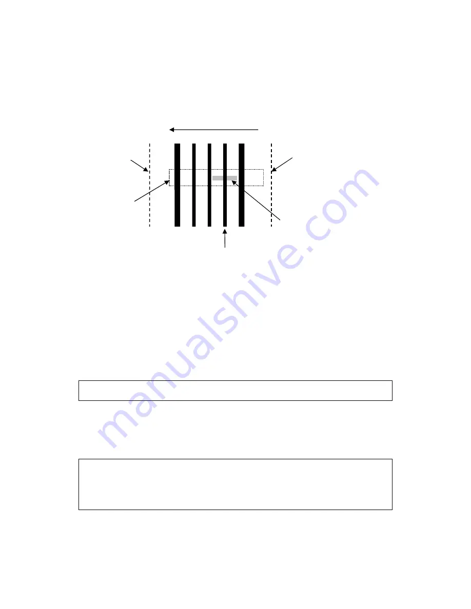
1) Suppose you have a series of dark lines printed on white paper, as shown below. The wide
lines are 0.050” [1.3mm] wide, the narrow lines are 0.025” [0.6mm] wide, and the lanes
between the lines are 0.100” [2.5mm] wide:
2) Now, let’s assume you want to track the narrow line closest to the right edge of the web.
Since there will probably be several lines in the sensor’s field of view you will need to indicate
which line you want the sensor to track.
a) Position the sensor so that it is approximately centered over the registration line.
b) Select the Calibration parameter and press ENTER to start the auto-calibration
procedure.
c) When the “Select line/edge” message appears, adjust the position and width of the
selection window so that it straddles the registration line and as much of the white area
around it as possible. Make sure the window
does not
touch the other lines nearby. Use
the DOWN key to adjust position and the UP key to adjust size.
Note:
It may not be necessary to adjust the selection window if there is only one line in
the sensor’s field of view and the sensor has been centered over it.
d) As you adjust the window size and position, the sensor will continuously analyze your
selection and pick the best parameter settings to track the line you selected. If it can
reliably track this line it will place an indicator dot directly under it.
e) If the indicator dot is not visible or is in the wrong place, adjust the selection window size
and position until the indicator appears under the desired line.
Tip:
To exit from the auto-calibration procedure without changing any settings, press the
UP key repeatedly until the “Exit?” message appears, then press ENTER.
Tip:
To track lines that vary greatly in width, press the UP key repeatedly until you see
the selection widow double in thickness. This mode widens the Min/Max parameter
tolerances to ± 50%. These parameters are described below.
3) When the indicator dot is under the line you want to track, press the ENTER key to complete
the auto-calibration. The sensor will then store the new parameter values in the current Job
Right edge of web
Scan direction (Right-to-Left)
Selection window
Left edge of web
Registration line
Sensor’s field of view
(0.625” [15.9mm] wide)
Summary of Contents for EVO 150
Page 1: ...P O Box 7816 Madison Wisconsin 53707 7816 Instruction Manual EVO 150 Web Guide Control System...
Page 2: ......
Page 6: ...EVO 150 Controller 4 EVO 150TM Web Guide Control System...
Page 56: ...PointSource and WideArray Edge Detectors 54 PointSource and WideArray Edge Detectors...
Page 62: ...AccuBeam 3 Digital Line Guide Sensor 60 AccuBeam 3 Digital Line Guide Sensor...
Page 85: ...AccuWeb Linear Actuators 83 AccuWeb Linear Actuators...
Page 90: ...Remote Station Guide Point Adjust 88 Remote Station Guide Point Adjust...
Page 99: ...Remote Station Auxiliary 97 Remote Station Auxiliary...
Page 104: ...Fieldbus Interface 102 Fieldbus Interface...
Page 124: ......
Page 125: ......
Page 126: ......
Page 127: ......
Page 128: ......
Page 129: ......
Page 130: ......
Page 131: ......
Page 132: ......
Page 133: ......
Page 134: ......
Page 135: ......
Page 136: ......
Page 137: ...NOTES...


