


EVO 150 Controller
8
Installation
The EVO 150 system has been tested, calibrated, and run at the factory in a closed-loop
configuration. After installation, most systems may be started up and operated without further
adjustment. Refer to the connection and wiring diagrams on page 121 for cable installation
information.
OEMs:
If shipping clamps and spreaders are removed, make sure that they are re-installed
prior to forwarding to the final destination. Verify that all mechanical and electronic
components are secured for shipment.
1. Linear Actuator and Guide
Install the web guide and linear actuator into the machine. Refer to the guide and actuator
application drawings on page 121 for installation information. Once the web guide is installed,
it must be trammed to the rest of the machine.
Note:
Make sure the actuator is in the servo-center position before tramming the web guide.
This may not be possible until after step 5, below.
Important:
Special attention must be given to the actuator mounting. Any mechanical
compliance or backlash in the actuator mounting will seriously affect guiding accuracy.
Deflections of a few thousandths of an inch will reduce the performance of the system. Also,
an anti-rotation bracket is required for most applications. The actuator must be allowed to
gimbal slightly on the ball rod ends to accommodate minor actuator mounting misalignment.
Note:
Motor contains no temperature-sensing device to protect motor from excessive
temperature due to failure-to-start or overload. Motor should be protected by other means in
accordance with the NEC and local code requirements.
2. Sensor (Edge Detector or Digital Line Guide)
Install the sensor (edge detector or digital line guide). Refer to the guide and sensor
application drawings on page 121 for installation information. Use of the AccuWeb edge
detector mounting bracket simplifies installation and adjustment.
The sensor cable should be long enough so that the sensor may be repositioned if the web
width or web path changes. The standard cable length is 12 feet. Longer cables are available
upon request.
Note:
The cables supplied with the system have been chosen for specific shielding and
capacitance properties. DO NOT splice or replace these cables with any other style or
configuration of cable. This can cause serious degradation or complete loss of system
performance. DO NOT SPLICE CABLES. Longer cables are available upon request.
3. Control
Enclosure
Install the control enclosure on a rigid mount such as a wall or secure framework. Do not
install the control enclosure on the side of a dryer or in other high temperature areas. Also, do
not install the control enclosure on a moving winder structure.
If no enclosure is provided, the controller assembly shall be enclosed in a Type 1 or similar
enclosure.
Summary of Contents for EVO 150
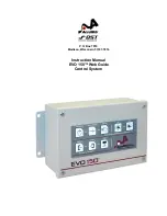
Page 1: ...P O Box 7816 Madison Wisconsin 53707 7816 Instruction Manual EVO 150 Web Guide Control System...
Page 2: ......
Page 6: ...EVO 150 Controller 4 EVO 150TM Web Guide Control System...
Page 56: ...PointSource and WideArray Edge Detectors 54 PointSource and WideArray Edge Detectors...
Page 62: ...AccuBeam 3 Digital Line Guide Sensor 60 AccuBeam 3 Digital Line Guide Sensor...
Page 85: ...AccuWeb Linear Actuators 83 AccuWeb Linear Actuators...
Page 90: ...Remote Station Guide Point Adjust 88 Remote Station Guide Point Adjust...
Page 99: ...Remote Station Auxiliary 97 Remote Station Auxiliary...
Page 104: ...Fieldbus Interface 102 Fieldbus Interface...
Page 124: ......
Page 125: ......
Page 126: ......
Page 127: ......
Page 128: ......
Page 129: ......
Page 130: ......
Page 131: ......
Page 132: ......
Page 133: ......
Page 134: ......
Page 135: ......
Page 136: ......
Page 137: ...NOTES...