L1
IL
1
IL
2
IL
3
L2
L3
Protected Object
CT 600/5
Star Connected
IL1
IL2
IL3
IED
IEC13000002-4-en.vsdx
1
2
3
4
SMAI2
BLOCK
REVROT
^GRP2L1
^GRP2L2
^GRP2L3
^GRP2N
AI3P
AI1
AI2
AI3
AI4
AI N
5
IN
IEC13000002 V4 EN-US
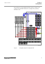
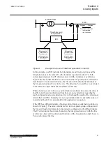
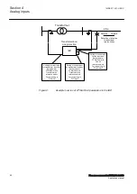
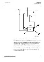
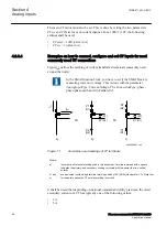
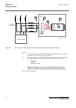
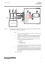
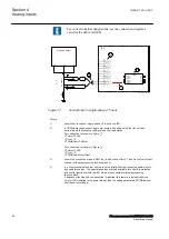
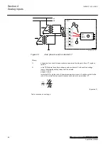
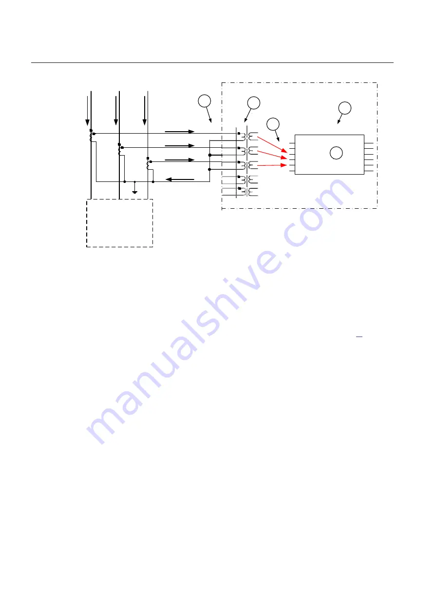
Figure 12:
Star connected three-phase CT set with star point towards the protected object
Where:
1)
The drawing shows how to connect three individual phase currents from a star connected
three-phase CT set to the three CT inputs of the IED.
2)
The current inputs are located in the TRM. It shall be noted that for all these current inputs
the following setting values shall be entered for the example shown in Figure
.
•
CTprim=600A
•
CTsec=5A
•
CTStarPoint=ToObject
Ratio of the first two parameters is only used inside the IED. The third parameter
(CTStarPoint=ToObject) as set in this example causes no change on the measured
currents. In other words, currents are already measured towards the protected object.
Table continues on next page
Section 4
1MRK 511 407-UEN C
Analog inputs
56
Phasor measurement unit RES670 2.2 IEC
Application manual
Summary of Contents for Relion RES670
Page 1: ...RELION 670 SERIES Phasor measurement unit RES670 Version 2 2 IEC Application manual...
Page 2: ......
Page 46: ...40...
Page 52: ...46...
Page 92: ...86...
Page 112: ...106...
Page 178: ...172...
Page 216: ...210...
Page 232: ...226...
Page 286: ...280...
Page 328: ...322...
Page 340: ...334...
Page 380: ...374...
Page 381: ...375...

