


8.2.2.3
Parallel transformer inrush current logic
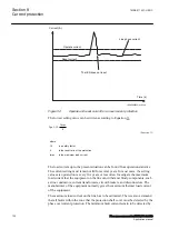
M15282-97 v6
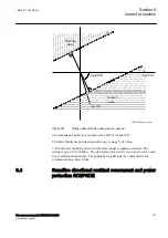
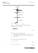
In case of parallel transformers there is a risk of sympathetic inrush current. If one
of the transformers is in operation, and the parallel transformer is switched in, the
asymmetric inrush current of the switched-in transformer will cause partial
saturation of the transformer already in service. This is called transferred
saturation. The 2
nd
harmonic of the inrush currents of the two transformers will be
in phase opposition. The summation of the two currents will thus give a small 2
nd
harmonic current. The residual fundamental current will however be significant.
The inrush current of the transformer in service before the parallel transformer
energizing, will be a little delayed compared to the first transformer. Therefore, we
will have high 2
nd
harmonic current initially. After a short period this current will
however be small and the normal 2
nd
harmonic blocking will reset.
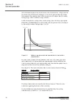
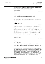
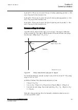
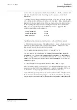
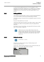
en05000136.vsd
Power System
IN>
IN>
IEC05000136 V1 EN-US
Figure 56:
Application for parallel transformer inrush current logic
If the
BlkParTransf
function is activated, the 2
nd
harmonic restrain signal will latch
as long as the residual current measured by the relay is larger than a selected step
current level. Assume that step 4 is chosen to be the most sensitive step of the four
step residual overcurrent protection function EF4PTOC. The harmonic restrain
blocking is enabled for this step. Also the same current setting as this step is chosen
for the blocking at parallel transformer energizing.
The settings for the parallel transformer logic are described below.
BlkParTransf
: This is used to
On
blocking at energising of parallel transformers.
UseStartValue
: Gives which current level should be used for the activation of the
blocking signal. This is given as one of the settings of the steps: Step 1/2/3/4.
Normally, the step having the lowest operation current level should be set.
8.2.2.4
Switch onto fault logic
M15282-106 v4
In case of energizing a faulty object there is a risk of having a long fault clearance
time, if the fault current is too small to give fast operation of the protection. The
switch on to fault function can be activated from auxiliary signals from the circuit
breaker, either the close command or the open/close position (change of position).
1MRK 511 407-UEN C
Section 8
Current protection
Phasor measurement unit RES670 2.2 IEC
137
Application manual
Summary of Contents for Relion RES670
Page 1: ...RELION 670 SERIES Phasor measurement unit RES670 Version 2 2 IEC Application manual...
Page 2: ......
Page 46: ...40...
Page 52: ...46...
Page 92: ...86...
Page 112: ...106...
Page 178: ...172...
Page 216: ...210...
Page 232: ...226...
Page 286: ...280...
Page 328: ...322...
Page 340: ...334...
Page 380: ...374...
Page 381: ...375...


