


Montaż i uruchomienie
Erection and
Commissioning
3
MNS DTR / MNS Service
43
3.5 Sposoby mocowania do fundamentu
3.5 Fastening methods to foundation
Do ustawienia rozdzielnicy z dolnym
podejściem kablowym konieczny
jest fundament z przepustami lub kanał kablowy.
Celki powinny być przede wszystkim ustawione na ramie fundamen-
towej, która jest osadzona:
w podłożu betonowym,
lub wspornikach, jako
podłoga techniczna.
Przy montażu ramy fundamentowej należy zwrócić uwagę na następu-
jące elementy:
rama fundamentowa w miarę możliwości powinna być wykonana
pod nadzorem monterów ABB lub przez nich sprawdzona,
n
a długości 1 m tolerancja ułożenia ramy w poziomie nie może
przekroczyć
1 mm. Należy to zapewnić przez użycie odpowied-
nich przyrządów niwelujących (np. poziomnica, łata),
r
ama nie może wykazywać żadnych pofałdowań (
zgodnie z DIN lSO 1101),
p
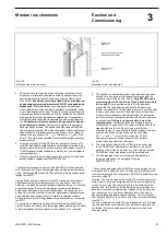
oziomowanie ramy fundamentowej może przebiegać np. przy
użyciu nastawialnego trzpienia PRESTOJACK (patrz Rys. 39).
Przy ustawianiu rozdzielnice są łączone z ramą przez spawanie lub
skręcanie (patrz Rys. 39).
Długość spawu w każdej celce
od czoła i strony tylnej
nie po-
winna być mniejsza niż 20 mm. Miejsca spawów należy chronić
przed korozją przez malowanie (np. farbą cynkową).
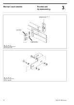
Do mocowania za pomocą śrub dostarczane są kątowniki. Otwory
do mocowan
ia metalowych kołków rozporowych M8 należy na-
wiercić podczas ustawiania (patrz Rys. 40).
W przypadku zastosowania
podłóg technicznych należy zwrócić uwa-
gę na:
zachowanie tolerancji jak w przypadku ramy fundamentowej,
nieprzekroczenie tolerancji
wynikającej z osiadania podłogi
(
szczególnie przy zastosowaniu wkładu izolacyjnego i klejącego).
w
ytrzymałość podłogi technicznej p=20 kN/m
2
(
obciążenie z góry
na dół).
Przy ustawianiu rozdzielnice są łączone z podwieszaną podłogą przez
spawanie lub skręcanie.
Długość spawu w każdej celce
od czoła i strony tylnej
minimum
20 mm.
Zapewnia to niezawodne połączenie z ziemią. Miejsca
spawów chronić przed korozją przez malowanie (np. farbą cynko-
wą).
W przypadku, gdy
spawanie jest niemożliwe, rozdzielnica może
być przykręcona do podłogi technicznej. Konieczne do tego otwory
należy wykonywać na budowie.
Należy zapewnić przyleganie każdej celki dolnymi profilami do po-
wierzchni podłogi. Ze względu na promień gięcia kabla oraz odpo-
wiedni
dostęp zaleca się, by minimalna wysokość podłogi wynosiła
500 mm.
The erection of switchgears having the cable entries at the
bottom requires a foundation with an opening or a cable duct.
The cubicles should preferably be erected on a base frame which
is either
embedded in the concrete fIoor or
rests as false floor on supports.
When erecting the base frame the following must be observed:
The base frame should be aligned and checked under the
supervision of an ABB fitter.
The horizontal tolerance of the frame must not exceed
±1 mm over a length of 1 m. This is to be ensured by using
suitable levelling devices (e.g. spirit level, 1 Mlong surveyors
rod).
The frame must not ondulate (
according to DIN lSO 1101)
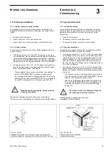
The leveIling of base frames can be performed e.g. with
PRESTOJACK levelling spindles (see fig. 39).
During erection the switchgear is welded or screwed to the base
frame (see fig. 39).
The length of the weld seams at the
front and rear
of each
cubicle should not be less than 20 mm. All weldings must be
protected against corrosion by a coat of paint (e.g. zinc
paint).
The screwed connection is carried out through the transverse
section. The mounting hoIes required for metal straddling
dowels M8 must be drilled during erection (see fig. 40).
When false floors are used, notice that:
Tolerances are the same as for the base frame.
The subsoil must be firm, so that the tolerances are not
exceeded by settling of the soil (especially when using
insulation layers and adhesives).
The false floor has to have a carrying capacity of p=20 kN/m
2
(Compression load from top to bottom).
During erection the switchgear is welded or screwed to the false
floor.
The length of the weld seams at the
front and rear
of each
cubicle should not be less than 20 mm. Then a reliable earth
connection is provided. All weldings must be protected
against corrosion by a coat of paint (e.g. zinc paint).
lf welding is not possible, the switchgear can be bolted to the
false floor. The necessary mounting holes should be driIled
on site.
Care should be taken to ensure that the base sections of each
cubicle rests evenly on the supports. Taking into account the
bending radius of the cables and adequate accessibility, a
minimum floor height of 500 mm is recommended.
2 / 1000
2 / 1000