


Montaż i uruchomienie
Erection and
Commissioning
3
MNS DTR /MNS Service
38
3.4 Posadowienie
3.4 Erection
3.4.1
Ustawienie i połączenie celek
3.4.1 Erection and connection of the cubicles
Ustawienie rozdzielnicy powinno być przeprowadzone w następujący
sposób:
1.
Ustawione w jednym rzędzie zestawy transportowe należy dokład-
nie wyrównać względem siebie. Należy uważać na to, aby roz-
dzielnice były wypoziomowane. Drzwi i osłony nie mogą być prze-
krzywione ani naprężone. Ustawianie można rozpoczynać z lewej
lub prawej strony.
2.
Konstrukcje zestawów transportowych należy skręcić ze sobą
(patrz Rys. 31). W tym celu w rozdzielnicach jednostronnych w
profilach pionowych zainstalowane są po 4 nitonakrętki M6 (w
każdym profilu znajdującym się po lewej stronie celki). W rozdziel-
nicach dwustronnych z możliwością operowania od frontu i od tyłu
nakrętki te mocowane są w profilach po lewej stronie celki i po
prawej stronie celki (patrz
ąc od frontu).
3.
Ściany boczne celek powinny być zamontowane. Należy do tego
użyć śrub M6x10 (patrz Rys. 33).
Podczas mocowania ścian na-
leży się upewnić, że przynajmniej jedno połączenie sieci
ochronnej je
st wykonane w miejscu usytuowania śruby
ochronnej.
4.
W przypadku braku dostępu do miejsc połączeń śrubowych profile
boczne mogą być połączone ze sobą przez zastosowanie dołą-
czonych do dostawy elementów połączeń konstrukcyjnych (patrz
Rys. 32).
Do pierwszego
wkręcenia śrub samogwintujących najlepiej zastoso-
wać wkrętak elektryczny lub pneumatyczny.
Momenty dokręcające połączeń śrubowych dla elementów konstruk-
cyjnych znajdują się w rozdziale 5.14.
The erection of the cubicles should be carried out, as described
in the following:
1. The shipping units which are to be erected in one row have to
be aligned accurately and checked that they are vertical.
Doors and panels must not be twisted or stressed. The
erection can start at the left or at the right.
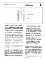
2. The frames of the shipping units have to be screwed together
(see fig. 31). The vertical sections for front operated units are
already fitted on the left front and rear with 4 special nuts. For
front and rear operated cubicles, the vertical sections at front
left and rear right are fitted with the special nuts.
3. The side walls for the end cubicles have to be fastened. For
this purpose, taptite or torx screws M6x10 (see fig. 33) have
to be used.
During fastening the side walls it has to be
made sure that at least at one bolted connection a
protective conductor connection is realised by placing a
contact washer underneath.
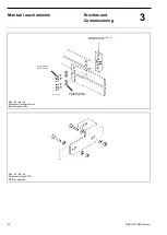
4. Additionally to the vertical sections or if the access to the
screw joints in the vertical sections is obstructed by installed
equipment, the bottom sections can be screwed together
using the frame connectors which are encIosed (see fig. 32).
For the initial tightening of the thread-forming screws an eIectric
or compressed-air operated screw-driver should be used.
For tightening torques for bolted frame connections refer to chap-
ter 5.14.
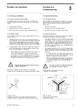
Rys. 31 / Fig. 31
Połączenie ram celek
Frame connection
Rys. 32 / Fig. 32
Dodatkowe łączenie ram celek
Additional frame connection
Wkręt łączący
Threaded rivet
Płytka łącząca
Spacer bar