


5 Installation and Commissioning
Product Manual, Control Cabinet IRC5P
87
5.6 Encoder and Sync Switch Installation
5.6.2 Encoder Specifications
General
The encoder is used to inform the robot control system of the position (motion) of
the conveyor to enable the tracking function to run the robot program correctly in
relation to the work objects on the conveyor. The tracking function is obtained by
installing the encoder on the conveyor and enter the signal from the encoder to the
control system via terminals in the control cabinet.
Encoder Type
The encoder must be of 2 phase type to enable registration of reverse conveyor
motion and to avoid ‘false counting’ related to vibration etc. when the conveyor is
not moving. The encoder can be PNP or NPN type.
Number of Pulses
The number of pulses per meter must be selected in relation to the speed of the
conveyor and the gearing between the encoder and the conveyor. The parameter
value should be between 1250 and 5000 cycles per meter.
In the following, we use this notion: Counts = cycles = 4 * pulse transitions. The
robot motion controller uses all the pulse transitions, so that the number of
increments used will be 4 times the number of full cycles from the encoder. The
system specifies only one count per cycle in the parameter (see pulse diagram in
). This means that the controller will read 5000 - 20000 pulses for the
encoder cycle ratio given above. Reducing the number of pulses below 5000 will
reduce the accuracy of the robot (5000 pulses/m = 0.2 mm/pulse). Increasing the
value beyond 10000 will have no significant effect as inaccuracies in robot and cell
calibration will be dominant. High values may however introduce a max. frequency
problem if long cables are used.
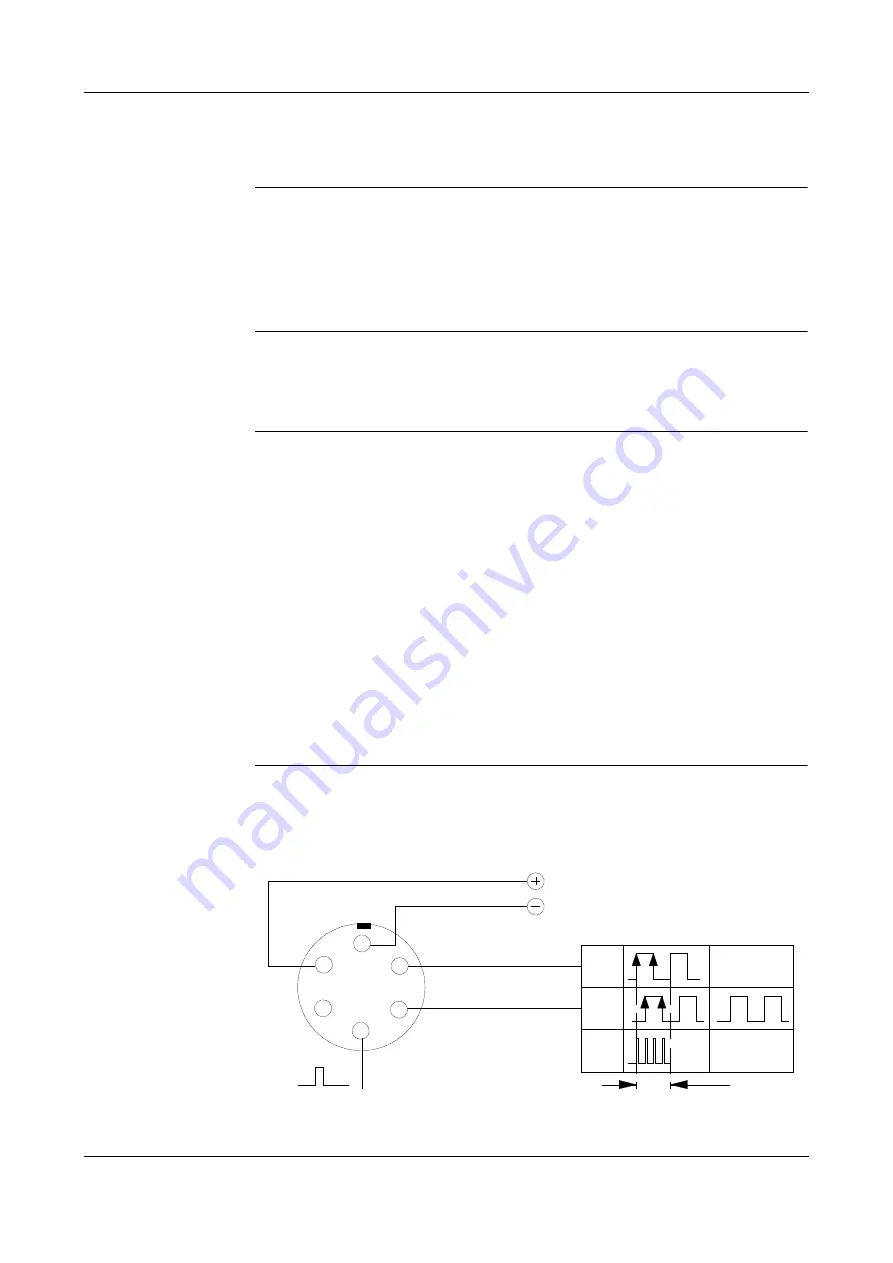
Recommended Encoder
The recommended Lenord and Bauer encoder shown below includes connections
for supply voltage and 2 output phases with 90° phase shift. The sync pulse
connection is not used.
Figure 37 Encoder connection - Lenord & Bauer
N
(Not used)
A
B
C
D
E
F
A+
B+
Encoder connector
(Mating face of connector
on encoder)
x4
2 phase
1 encoder cycle = 1 count
0°
90°
Single phase
(not used)
Internal used = 4 counts
Summary of Contents for IRC5P
Page 1: ...The heart of Robotics Product Manual Control Cabinet IRC5P 3HNA009834 001 en Rev 06 ...
Page 2: ......
Page 10: ...10 3HNA009834 001 en Rev 06 Product Manual Control Cabinet IRC5P ...
Page 14: ...2 Safety 14 3HNA009834 001 en Rev 06 Product Manual Control Cabinet IRC5P ...
Page 218: ...218 3HNA009834 001 en Rev 06 Product Manual Control Cabinet IRC5P Manual Status ...