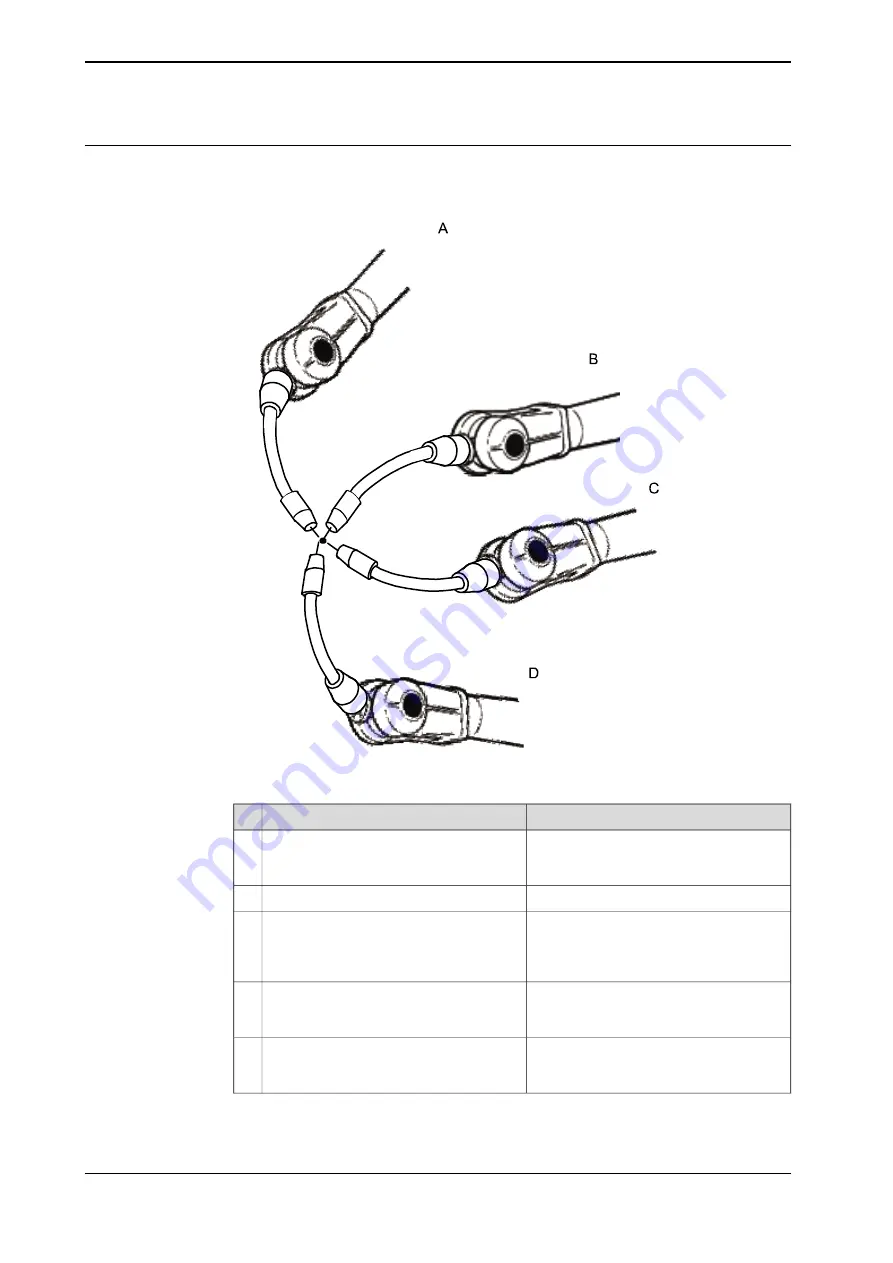
How to proceed with tool frame definition
This procedure describes how to define the tool center point in Cartesian
coordinates.
en0400000906
Information
Action
Use small increments to accurately posi-
tion the tool tip as close to the reference
point as possible.
Jog the robot to an appropriate position,
A, for the first approach point.
1
Tap
Modify Position
to define the point.
2
Jog away from the fixed world point to
achieve the best result. Just changing the
tool orientation will not give as good a
result.
Repeat step 1 and 2 for each approach
point to be defined, positions B, C, and D.
3
Follow the instructions in
If the method you are using is TCP&Z or
TCP&Z,X orientation must be defined as
well.
4
If, for some reason, you want to redo the
calibration procedure described in step 1-
4, tap
Positions
and then
Reset All
.
5
Continues on next page
182
Operating manual - IRC5 with FlexPendant
3HAC050941-001 Revision: G
© Copyright 2018 ABB. All rights reserved.
5 Programming and testing
5.5.4 Defining the tool frame
Continued
Summary of Contents for IRC5 with FlexPendant
Page 1: ...ROBOTICS Operating manual IRC5 with FlexPendant ...
Page 14: ...This page is intentionally left blank ...
Page 120: ...This page is intentionally left blank ...
Page 146: ...This page is intentionally left blank ...
Page 240: ...This page is intentionally left blank ...
Page 286: ...This page is intentionally left blank ...
Page 294: ...This page is intentionally left blank ...
Page 298: ...This page is intentionally left blank ...
Page 304: ......
Page 305: ......


