


30
User Guide
Setting advanced processing parameters
CoreSense M10 allows you to apply certain advanced processing parameters depending on your
situation. The procedures below briefly explain how to enable these processing parameters.
With the CoreSense M10, it is possible to add additive and/or multiplicative correction factors to raw
sensor data. In CoreSense M10, multiplicative factors are known as
slopes
and additive factors, as
offsets
.
For example, a slope of 1.1 applied to a concentration value of 100 ppm brings the raw sensor
measurement to 110 ppm.
As for offsets, an offset of -5 applied to a concentration of 100 ppm brings raw sensor measurement to
95 ppm.
The
Minimum threshold
parameter is an advanced filtering function for each sensor. When activated
any value lower than threshold value is set to 0. This corrected data is shown on dashboard, history data
and published protocols. The raw data is still available in the .csv file export. By default the minimum
threshold is set to the minimum level of detection as per instrument specifications. The function can be
deactivated by setting the value to zero (0).
To enter such values:
1
Click
Advanced settings
next to the
Apply
button. A confirmation dialog box appears.
2
Click
OK
. This activates the
Post-processing(opt)
and
Oswald efficiency
sections.
The
Advanced settings
button becomes
Basic settings
.
3
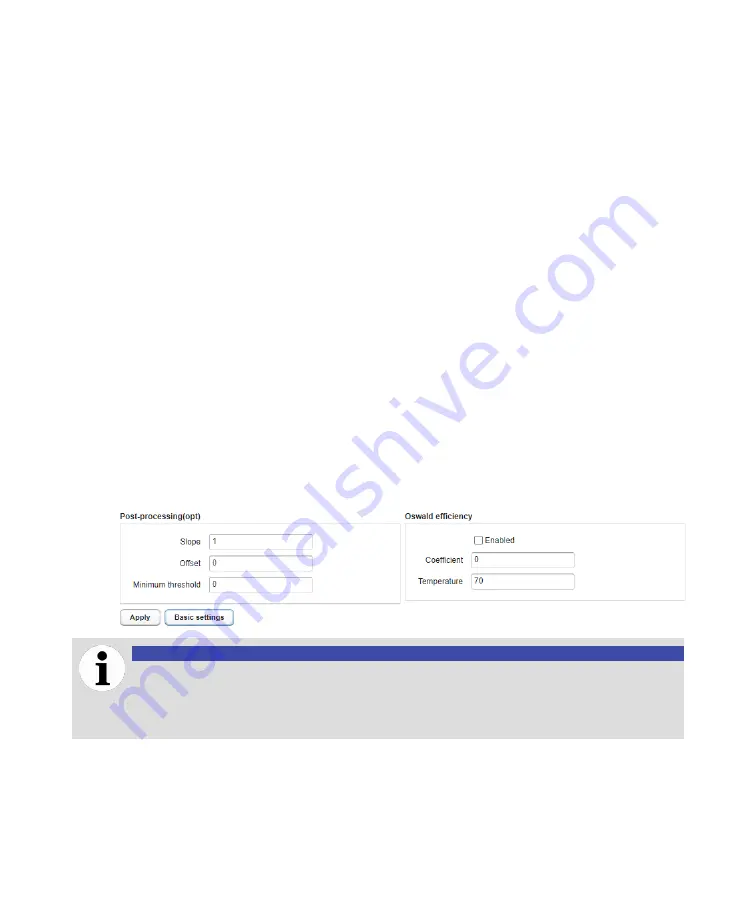
Enter the relevant values
Post-processing(opt)
section.
4
Click
Apply
to save your changes.
—
Figure 29
Entering advanced processing parameters
NOTICE
The
Oswald efficiency
coefficient is an advanced feature that must only be used with
the help or in the presence of your service representatives. Modifying parameters in this
section without any help could damage the system and render it unusable or, at the very
least, unreliable.
Summary of Contents for CoreSense M10
Page 1: ... USER GUIDE CoreSense M10 Multi gas monitoring system ...
Page 8: ...Page intentionally left blank ...
Page 18: ...Page intentionally left blank ...
Page 24: ...Page intentionally left blank ...
Page 26: ...22 User Guide Figure 19 Selecting an input channel ...
Page 36: ...Page intentionally left blank ...
Page 44: ...Page intentionally left blank ...
Page 56: ...52 User Guide ...
Page 62: ...Page intentionally left blank ...
Page 66: ...Page intentionally left blank ...
Page 107: ......


