background image

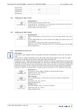
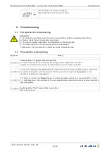
Heating Pband

Heating Pband

Setting range: 0.1..10.0 K
Factory setting: 2.0 K

Heating minimum

Heating minimum

Setting range: 0...100 %
Factory setting: 0 %

Heating maximum

Heating maximum

Setting range: 0...100 %
Factory setting: 100 %

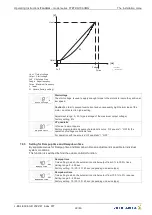
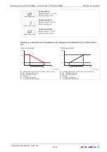
Heating or cooling function dependent on the setting in the installation menu 

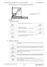
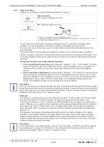
Heat actual <

set

 Heating function

H

max.

12.08.2008

v_heiz_0_10_heiz.vsd

S / V

A [°C]

M [%]

H

min.

R

M

Heating circuit level control (without output curve)

H max

Heating maximum

H min

Heating minimum

R

Pband

S / V O

set or Setpoint

A

Compartment temperature

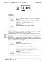
 Cooling function

H

max.

12.08.2008

v_heiz_0_10_kuehl.vsd

S / V

A [°C]

M [%]

H

min.

R

M

Heating circuit level control (without output curve)

H max

Heating maximum

H min

Heating minimum

R

Pband

S / V O

set or Setpoint

A

Compartment temperature

Operating Instructions 

Fcontrol


 model series FTET4/6/10AHMQ

Settings for operation

L-BAL-E094-GB 2022/47 Index 007

Part.-No. 

35/46

Содержание Fcontrol FTET4AHMQ

Страница 1: ...Fcontrol FTET4 6 10AHMQ Frequency inverter with integrated sine lter for 1 fans in agriculture Operating Instructions Keep for reference L BAL E094 GB 2022 47 Index 007 Part No english...

Страница 2: ...4 Installation location for agriculture 9 4 5 Temperature in uences during commissioning 9 5 Electrical installation 9 5 1 Safety precautions 9 5 2 EMC compatible installation 9 5 2 1 Motor cable 9 5...

Страница 3: ...2 Procedure for commissioning 26 9 Settings for operation 27 9 1 Quickinfo setpoint min and max compartment temperatures 27 9 2 Setting Ventilation 28 9 2 1 For the regulation of the fan 28 9 2 2 For...

Страница 4: ...lity Concurrence between the contents of these operating instructions and the described hardware and software in the device has been examined It is still possible that non compliances exist no guarant...

Страница 5: ...he instructions of AEL DLG VdS 2 4 Requirements placed on the personnel due diligence Persons entrusted with the planning installation commissioning and maintenance and servicing in connection with th...

Страница 6: ...he device Attention Automatically restart after a power failure or mains disconnection 2 7 Modi cations interventions in the device Attention For reasons of safety no unauthorized interventions or mod...

Страница 7: ...ective Sine lter phase to phase and phase to ground an absolute parallel control of fans without risk of damage for motors is possible Screened motor cables not required 3 3 Service work The device m...

Страница 8: ...n where it will not be disturbed but at the same time can be easily accessed Depending on the housing model cut o necessary cable inlets respectively to the cable diameter Or alternative use cable inl...

Страница 9: ...rohibited because energized exposed parts are present inside the device Disregarding this regulation can lead to severe personal injury For metal cable inlets the necessary protective earth connection...

Страница 10: ...epends on the design of the low voltage system on which the device is to be operated The assessment whether or which residual current protective device should be used is the responsi bility of the sys...

Страница 11: ...K1 and K2 in case of a motor fault if there are no other faults Relays K1 Fault Alarm At K1 inversion o factory set se IO Setup the relay drops out terminals 11 12 bridged At K1 inversion on se IO Se...

Страница 12: ...Setup see Installation menu 5 9 Fault input Digital In 1 D1 The fault input terminals D1 D1 an only be used to indicate an existing fault e g when an S ET10 type motor protection device trips The con...

Страница 13: ...for the control voltage cannot exceed 30 V between the GND and PE conductor terminals A connection to the PE conductor potential can be made if required t a bridge between the GND terminal and the PE...

Страница 14: ...enu 6 3 Menu operation Selection of the menu group to the right through the down key to the left through the up key By pushing the P button one reaches individual menu items in the menu group e g to g...

Страница 15: ...pear after approx 5 sec Once this menu is open this time delay is no longer active for approx 15 minutes after the last key con rmation Other than that operation in the installation is no di erent fro...

Страница 16: ...s not go under setting Min speed Msco ON It takes place a disconnection from setting Min speed to 0 if the given di erence is reached related to the desired value At a plus value before reaching the d...

Страница 17: ...the ventilation level control is less than the vantilation link the shutter position is calculated as in the following Shutter position Ventilation level control ventilation link 100 Example Ventilat...

Страница 18: ...artment temperature is greater than the increased set point this results in a higher ventilation minimum summer minimum If the compartment temperature falls under the increased setpoint the tolerance...

Страница 19: ...Attention is advised when operating with the output characteristic curve without invert ing A1 output curve A1 output curve OFF factory setting ON programming of curve active to see the following char...

Страница 20: ...tor modulation is present Parameter Factory setting User Setting MotorRatedCurr 6 0 A MotorRatedVolt 230 V Edgefrequency 50 0 Hz Max Frequency 50 0 Hz Rampup time 10 sec Rampdown time 10 sec Shutdown...

Страница 21: ...ts e g fans and pump operation an optimal speed control is generally achieved through this In systems in which high dynamics are required switchover to a linear characteristic must take place Generall...

Страница 22: ...curve UF square ON for the operation of voltage controllable fans For operation with linear curve UF quadratic OFF 7 8 5 Setting for Rampup time and Rampdown time By separate menus for Rampup time and...

Страница 23: ...disconnection to occur after modulation returns to a fast rotating motor Additionally the brake function can avoid that a fan which is switched o be driven in the wrong direction e g when a draft turn...

Страница 24: ...Test required The min speed adjustment must be set to 0 7 8 8 Setting Boost value The boost function is an automatic voltage increase when the control system is under dynamic requirements When using t...

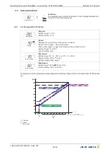
Страница 25: ...perating condition of the device Temperature IGBT Display of the internal temperature of the power semiconductor During impermissibly high levels at 75 C the output power is automatically reduced At 9...

Страница 26: ...rtently starting up before con guration is complete Settings for U f characteristic can only be made when no motor modulation is present 2 Set the menu language in the Quick Info menu if necessary To...

Страница 27: ...again Language Language Menu language by the factory set to German In this menu di erent national languages can be selected GB English D German PIN PIN The presets can be stored and reset using PIN c...

Страница 28: ...e control Setting range 2 0 20 0 K Factory setting 4 0 K Min Speed Min Speed Setting range O 6 100 O 12 50 Hz Factory setting 20 18 Hz Setting exceeds Max speed Max Speed Max Speed Setting range 100 5...

Страница 29: ...range 100 0 Factory setting 100 Example Setpoint ventilation 25 0 C O set 5 0 K Pband 10 0 K Kmax 19 08 2008 v_klappe_pte vsd S V A C K Kmin R K Flap opening in without output curve K max Shutter Max...

Страница 30: ...temperature sinks quickly the ventilation function can react quickly and reduce ventilation Information Of course this function can result in a higher set point on warm days But this set point is more...

Страница 31: ...ng compartment temperature of the Abteiltemperatur des Alarm Maximum value If the supply air temperature is greater than Alarm maximum and the compart ment temperature rises above the supply air tempe...

Страница 32: ...ast fault messages can be queried in the alarm list Overtemp Latest alarm overtemperature P 00029 49 07 Controllers period of operation at time of message 9 4 Settings for heating Heating Heating The...

Страница 33: ...he hysteresis is above the switch on point Negative hysteresis value Cooling function Relay OFF if the temperature around the hysteresis is below the switch on point Setting range 10 10 K Factory sett...

Страница 34: ...value Cooling function 0 1 12 08 2008 v_heiz_neg_hys_abs vsd H S A C H Hysteresis S Setpoint A Compartment temperature 0 Heating OFF 1 Heating ON 9 4 2 Controlling the heating via the 0 10 V signal l...

Страница 35: ...v_heiz_0_10_heiz vsd S V A C M Hmin R M Heating circuit level control without output curve H max Heating maximum H min Heating minimum R Pband S V O set or Setpoint A Compartment temperature Cooling f...

Страница 36: ...Value 18 7 Temp max Value 25 9 Reset Min Max OFF Language D PIN Version 1 00 OTC 00046 37 12 OTM 00046 37 12 Ventilation Setpoint 20 C Pband 4 0 K Min Speed 20 Max Speed 100 Shutter o set 1 0 K Shutte...

Страница 37: ...mperature OFF K1 Invert OFF K2 Invert OFF A1 Inverting ON A1 output curve OFF A2 Inverting OFF A2 output curve OFF Output curve P0 20 Output curve P1 50 Output curve P2 70 Output curve P3 82 Output cu...

Страница 38: ...on1 AUS Range1 min Range1 max Suppression2 AUS Range2 min Range2 max Suppression3 AUS Range3 max Range3 max Diagnostic Temperature IGBT 25 6 C Temperature ELKO 32 0 C Temperature SIFI 29 1 C DC Voltag...

Страница 39: ...the input E1 actual value 50 0 C Check the sensor lead and connection Sensor E2 Short circuit or interruption in the sensor lead to input E2 Short circuit E2 actual value 50 0 C interruption E2 actual...

Страница 40: ...s Check the temperature in the device via diagnostic menu Check cooling of the controller Sine lter Sine lter to hot Switch OFF at 150 C switch ON when cooled down to 70 C Check temperature in control...

Страница 41: ...f the internal relay 2 A 250 V AC Max permissible ambient temperature 55 C Min permissible ambient temperature 0 C if mains voltage is not switched o up to 20 C Permissible installation height 0 4000...

Страница 42: ...mperature see following table The average value measured during a 24 h period must be 5 K under the max ambient temperature For installation in a switch cabinet the device s dissipation and its possib...

Страница 43: ...utter Folgeregler Slave controller Abteiltemperatur Cot temperature Analog In 2 KTY 81 210 PT 1000 UMPO09K1 02 12 2009 Imax 6 mA Imax 6 mA Fcontrol FTET4 6 10AHMQ St rungseingang Fault input 6 3 4 5 1...

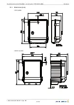
Страница 44: ...12 3 Dimensions mm FTET4AHMQ FTET6 10AHMQ Operating Instructions Fcontrol model series FTET4 6 10AHMQ Enclosure L BAL E094 GB 2022 47 Index 007 Part No 44 46...

Страница 45: ...ilation 15 Minimum space requirement 7 Minimum speed cut o 15 motor feed cable 8 motor leads 9 motor protection unit 9 O o set 16 one quadrantdrives 6 Operation 25 Outdoor installation 7 output charac...

Страница 46: ...de http www ziehl abegg com 12 6 Service note If you have any technical questions while commissioning or regarding malfunctions please contact our technical support for control systems ventilation te...

Отзывы: