5.5.2
Disconnection between controller and motor (repair switch)
Ideally, a repair switch should be installed
before the controller
(supply line disconnect).
In case of complete shutdown (total load) after the controller this may take place under some circum-
stances at full fan level of the controller. This can lead to an overcurrent protection switch-o
ff
.
5.6
Motor protection
The motor can be protected by connecting thermostats
“
TB
”
.
When multiple motors are connected, it is essential to ensure that thermostats
“
TB
”
are always
connected in series.
If a connected thermostat is tripped (break between the two terminals
“
TB - TB
”
), the device is
switched o
ff
and is not switched back on.
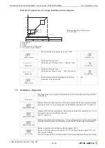
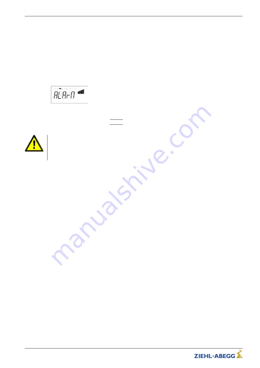
Motor fault
Display during motor fault
Possibilities for re-starting after the drive has cooled down (terminals
“
TB
”
bridged) by:
•
Main switch to position
“
0
”
=
|
STOP
|
and back to position
“
Auto
”
.
•
By switching the mains voltage o
ff
and then on again.
Attention!
•
An outside voltage may never be connected to the terminals
“
TB
”
!
•
If a bypass circuit is installed, or in the
“
100 %
”
position on devices with a main switch, the motor
protection inside the controller has no function. In this case, additional motor monitoring may be
required.
Behaviour of the relays K1 and K2 in case of a motor fault (if there are no other faults):
Relays K1 = Fault / Alarm
•
At K1 inversion = o
ff
(factory set se IO Setup) the relay drops out = terminals 11 - 12 bridged.
•
At K1 inversion = on (se IO Setup)the relay pulls up = terminals 11 - 14 bridged.
"
I.e. a motor fault is reported by the relay.
Relays K2 = Heating
•
At K2 inversion = o
ff
(factory set se IO Setup) and inactive heating (relay dropped out) the relay
remains dropped out (terminals 21 - 22 bridged).
•
At K2 inversion = o
ff
(factory set se IO Setup) and active heating (relay pulled up terminals 21 - 24
bridged) the relay drops out (terminals 21 - 22 bridged).
•
At K2 inversion = on (se IO Setup) and inactive heating (relay pulled up) the relay remains pulled
up (terminals 21 - 24 bridged).
•
At K2 inversion = on (se IO Setup) and active heating (relay dropped out = terminals 21 - 22
bridged) the relay pulls up (terminals 21 - 24 bridged).
"
I.e. the heating is switched o
ff
in the even of a motor fault.
5.7
Sensor connection (E1, E2)
The device has 2 analogue inputs for temperature sensors type TF.. (KTY81-210) or PT1000 :
•
For Compartment temperature
–
Sensor type TFR (Part.-No. 00089846) in scope of delivery
–
Terminals
“
E1
”
/
“
T1
”
•
For the out door temperaure or separate sensor for shutter or heating
–
Input factory setting deactivated
–
Terminals
“
E2
”
/
“
T2
”
–
Sensor not in scope of delivery
Operating Instructions
Fcontrol
–
model series FTET4/6/10AHMQ
Electrical installation
L-BAL-E094-GB 2022/47 Index 007
Part.-No.
11/46


