


5.3
Mains connection
5.3.1
Mains voltage
The mains connection is made at the terminals: PE, L1 and N. In this regard, it is essential to ensure
that the mains voltage lies within the allowable tolerance speci
fi
cations (see technical data and rating
plate a
ffi
xed to the side).
A connection between two phase conductors is possible for 3 ~ 230 V supply networks.
Attention!
To activate the on current limitation, you must wait at least 90 seconds after switching o
ff
the line
voltage before switching back on!
5.3.2
Required quality attributes for the mains voltage
Danger due to electric current
The mains voltage must comply with the EN 50160 quality characteristics and the de
fi
ned standard
voltages in IEC 60038!
5.3.3
Leakage current, securely attached, protective earth conductor
Danger due to electric current
The maximum leakage current depends on the type of device and the connected mains voltage (see
Technical Data). With regard to
fi
xed connection and the type of PE conductor connection, the
speci
fi
cation for the leakage current must be observed under consideration of the locally valid
standards (for Europe see EN 50178 Section 5.2.11 or 5.3.2.1 etc.).
Minimum cross-section for PE conductor for
fi
xed connection = 1.5 mm
2
!
5.4
Systems with residual current protective devices
Whether the use of a residual current protective device (RCD) is necessary or allowed depends on the
design of the low-voltage system on which the device is to be operated.
The assessment whether or which residual current protective device should be used is the responsi-
bility of the system operator or electrician commissioned by it.
Danger due to electric current
When selecting the tripping characteristics of the residual current protective device, the possible
residual current form of the power electronics (system with semiconductors) must be observed in
conjunction with the standards and regulations applicable at the place of use.
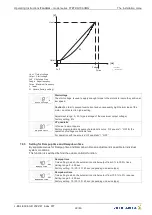
Design of the power electronics
•
The design of the power electronics corresponds to a frequency inverter with two-pulse bridge
circuit and PFC (power factor correction).
Information
To prevent false tripping due to pulse-like charging currents of the integrated EMC
fi
lter, we
recommend a rated di
ff
erential current of 300 mA for reasons of operational reliability in the case of
fi
xed connection and use of a residual current protective device.
5.5
Inverter output
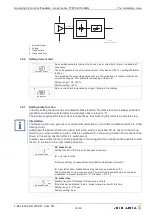
5.5.1
Motor connection
The motor leads are connected to the terminals: U1, U2. Several fans can be connected to the
controller-the maximum total current of all motors must not exceed the current rating for the controller.
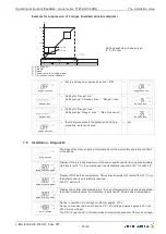
Change direction of rotation
wiring diagram fan!
Information
•
It is recommended that a separate motor protection unit be foreseen for each fan.
•
For motors with thermistors
“
TB
”
e.g. type S-ET10.
Operating Instructions
Fcontrol
–
model series FTET4/6/10AHMQ
Electrical installation
L-BAL-E094-GB 2022/47 Index 007
Part.-No.
10/46


