


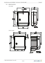

9.2.3
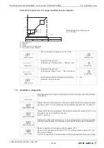
Setpoint derating
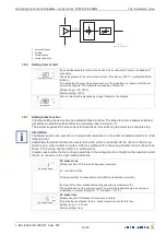
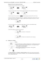
Activation for automatic reduction (Setpoint automatic in summer)
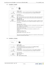
Setp. Derating
Setpoint derating
OFF
= Setpoint derating switched o
ff
Setp. Derating
ON
= Setpoint derating switched on
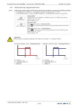
05.08.2008
v_absenkauto_aktiv_pte.vsd
1
2
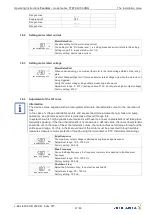
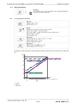
1
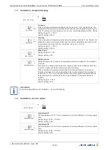
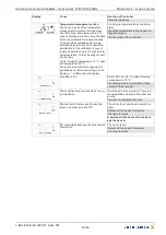
Display for automatic set point adaptation is active
2
New nominal set point with active automatic set point derating e. g. set point 25.0
°
C plus
automatical increasing 0.2 K/h
The automatic reduction feature,
“
automatic setpoint derating
”
, is intended to help operate the
ventilation in an area adapted to the ambient conditions, especially during the summer.
To achieve this, the controller takes over the control of the setpoint (if the automatic reduction has
been activated).
This function has the task of always controlling the setpoint in such a manner that the ventilation
function is always in a position to apply control and thus quickly react to temperature
fl
uctuations. This
is of prime importance during temperature drops in the summer caused by thunderstorms and similar
in
fl
uences.
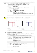
The function observes the compartment temperature:
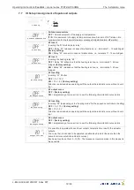
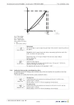
1.
If the compartment temperature
rises above the
“
setpoint
”
+ the
“
control range
”
, the active
setpoint is increased via an automatic timer per hour by the adjustable value (e.g. 0.2 K/h). The
increase is only carried out up to a max. value (
“
Max. increas
”
can be set in the installation
menu).
2.
If the compartment temperature
sinks below the
“
Setpoint
”
+ the
“
Pband
”
, the active nominal
value is reset via an automatic timer per hour by the adjustable value back down to the
“
normal
setpoint
”
) (
“
Setpoint
”
in the
“
Ventilation
”
menu) (e.g. 0.1 K/h). This ensures the ventilation control
always works directly at the end of the control range. If the compartment temperature sinks
quickly, the ventilation function can react quickly and reduce ventilation.
Information
Of course, this function can result in a higher set point on warm days. But this set point is more realistic
and is thus the ideal set point for the prevailing ambient conditions. Increasing the set point only a
ff
ects
the ventilation set point; all other nominal values for heating, shutters, minimum-air disconnect and the
additional controllers remain at the
“
normal setpoint
”
.
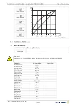
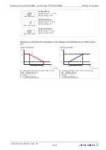
Examples
Let
’
s assume your desired setpoint in the compartment is 20.0
°
C (control range 5.0 K). This setpoint
can surely be reached in the winter because the supply air in this season is generally cooler.
On warm summer days, e.g. 28
°
C, this setpoint cannot be attained as the supply air is signi
fi
cantly
warmer. That means, you warm up the compartment with a supply air temperature that is too high. But
your setpoint is set to 20
°
C! The result: 100 % ventilation takes place. If the supply air temperature
then quickly falls, 100% ventilation is carried out until the compartment temperature eventually falls
below 25
°
C.
That causes a high degree of temperature
fl
uctuations, which can lead to diseases in the animal
population. One remedy could be to manually increase the setpoint or the control range, but these
changes would have to be constantly adapted to the corresponding ambient conditions. And that is
where the automatic reduction function takes over. This function relieves you of the work of having to
constantly modify the setpoint manually.
Information
As the temperature only indirectly gives evidence of the air quality, a su
ffi
cient minimum ventilation
must absolutely be ensured for this function. The automatic reduction makes allowance for this
situation (see Settings
“
Minimum extra
”
in installation menu).
Operating Instructions
Fcontrol
–
model series FTET4/6/10AHMQ
Settings for operation
L-BAL-E094-GB 2022/47 Index 007
Part.-No.
30/46


