


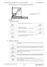


5.10
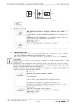
Relay outputs (K1, K2)
The controller has two relay outputs (contact rating see technical data):
•
For Fault indication Relays K1
–
Connection of the
fl
oating contacts to the terminals 11, 12, 14.
–
For operation the relay is energized i.e. terminals
“
11
”
and
“
14
”
are bridged (factory setting not
inverted).
–
In case of power failure, motor fault (
“
TB
”
interruption), external fault (D1), temperature fault, the
fault signal relay drops out, the terminals
“
11
”
and
“
12
”
are bridged.
–
The fault signal over the relay can be acknowledged with the
|
ESC
|
-key combination. In such a
way the error remains existing (e.g. sensor fault) comes after an adjustable time interval again a
message (factory setting alarm pause 60 min (see Alarm).
•
For Heating Relays K2
–
Connection of the
fl
oating contacts to the terminals 21, 22, 24.
–
For heating
“
ON
”
relay energized i.e. terminals
“
21
”
,
“
24
”
bridged (factory setting not inverted).
Information
Inverting relay function in IO Setup possible.
5.11
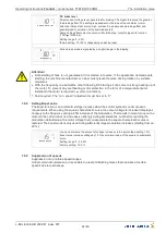
Potential at control voltage connections
The connections for the control voltage (< 30 V) relate to the common GND potential (exception: relay
contacts are potential-free). There is a potential isolation between the connections for the control
voltage and the PE conductor. It must be ensured that the maximum external voltage at the con-
nections for the control voltage cannot exceed 30 V (between the
“
GND
”
and
“
PE
”
conductor
terminals). A connection to the PE conductor potential can be made if required;
fi
t a bridge between
the
“
GND
”
terminal and the
“
PE
”
connection (terminal for shield).
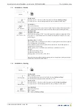
6
Controls and Menu
6.1
switches
0
Power stack (fan) is switched o
ff
Display: Compartment o
ff
, symbol
|
STOP
|
, fan level =
“
0
”
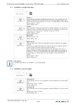
Messages at overtemperature and undertemperature via display and relay K1 are switched
o
ff
.
Messages motor fault (TB) and external fault (D1) via display and relay (K1) are
not
switched
o
ff
.
The heating via relay (K2) and output 0...10 V (A2) is switched o
ff
.
The exhaust air
fl
ap via output 0...10 V (A1) is opened (=> A1 inverted at factory = 0 V, A1 not
inverted = 10 V).
Auto
Power stack in operation (standard position)
100 %
Ventilators are operated directly from the mains with no control.
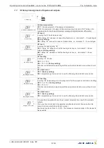
Motor protection by thermostat connection input
“
TB
”
without function!
Display: Compartment o
ff
, symbol
|
STOP
|
, fan level =
“
0
”
Messages at overtemperature and undertemperature via display and relay K1 are switched
o
ff
.
Messages motor fault (TB) and external fault (D1) via display and relay (K1) are
not
switched
o
ff
.
The heating via relay (K2) and output 0...10 V (A2) is switched o
ff
.
The exhaust air
fl
ap via output 0...10 V (A1) is opened (=> A1 inverted at factory = 0 V, A1 not
inverted = 10 V).
Information
The display is in operation in every switch position! (cannot be switched o
ff
)!
Operating Instructions
Fcontrol
–
model series FTET4/6/10AHMQ
Controls and Menu
L-BAL-E094-GB 2022/47 Index 007
Part.-No.
13/46


