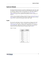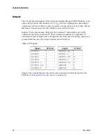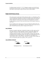
39
Auxiliary Audio
Auxiliary Audio
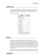
The console has additional audio signals available on connector P1 at the rear of the unit.
Most of these signals are used when installing optional equipment. The mating screw
terminal connector is supplied with the console. The connector pinout is listed in
Table 10: Auxiliary Audio
Labeling
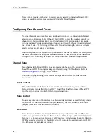
The push button switches of the control panels usually come from the factory with
customer specified labeling installed. If for any reason, the labeling needs to be changed,
the labels may be replaced in the field. Spare clear key tops are provided with the unit for
future modification. The key tops are accessible by removing the push-button key top
from its plastic plunger. Grasp the key top with thumb and forefinger placed on horizontal
edges of the key. Gently pull the key top off. Pliers may be used, but care must be taken so
not to slip and scratch the cover. Only the outer portion of the key should be grasped when
removing to allow the lower locking rib to release. Use a rocking motion to release one
side at a time.
Labels may be made of white or colored typing paper, upon which the desired words have
been typed or photocopied. Guidelines for cutting the label to the proper size may be made
Signal
P1 Pin #
BUSY OUT
1
SELECT AUDIO OUT
2
AUX AUDIO IN
3
AUX AUDIO COMMON
4
AUX PTT IN
5
PTT COMMON
6
D. MIC AUD IN+
7
D. MIC AUD IN–
8
D. MIC PTT IN
9
PTT COMMON
10
MONITOR SW IN
11
MON COMMON
12
FOOTSWITCH
13
FS COMMON
14
COMB AUDIO OUT*
15
* Set JP1 to position B to enable unselect
audio at pin 15. See
Содержание 4010
Страница 1: ...Model 4010 Radio Dispatch Console Installation and Programming 025 9227S ...
Страница 46: ...Console Installation 46 025 9227S ...
Страница 78: ...Option Installation 78 025 9227S ...
Страница 134: ...Appendix D Troubleshooting 134 025 9227S ...

