33
Wiring to the Channels
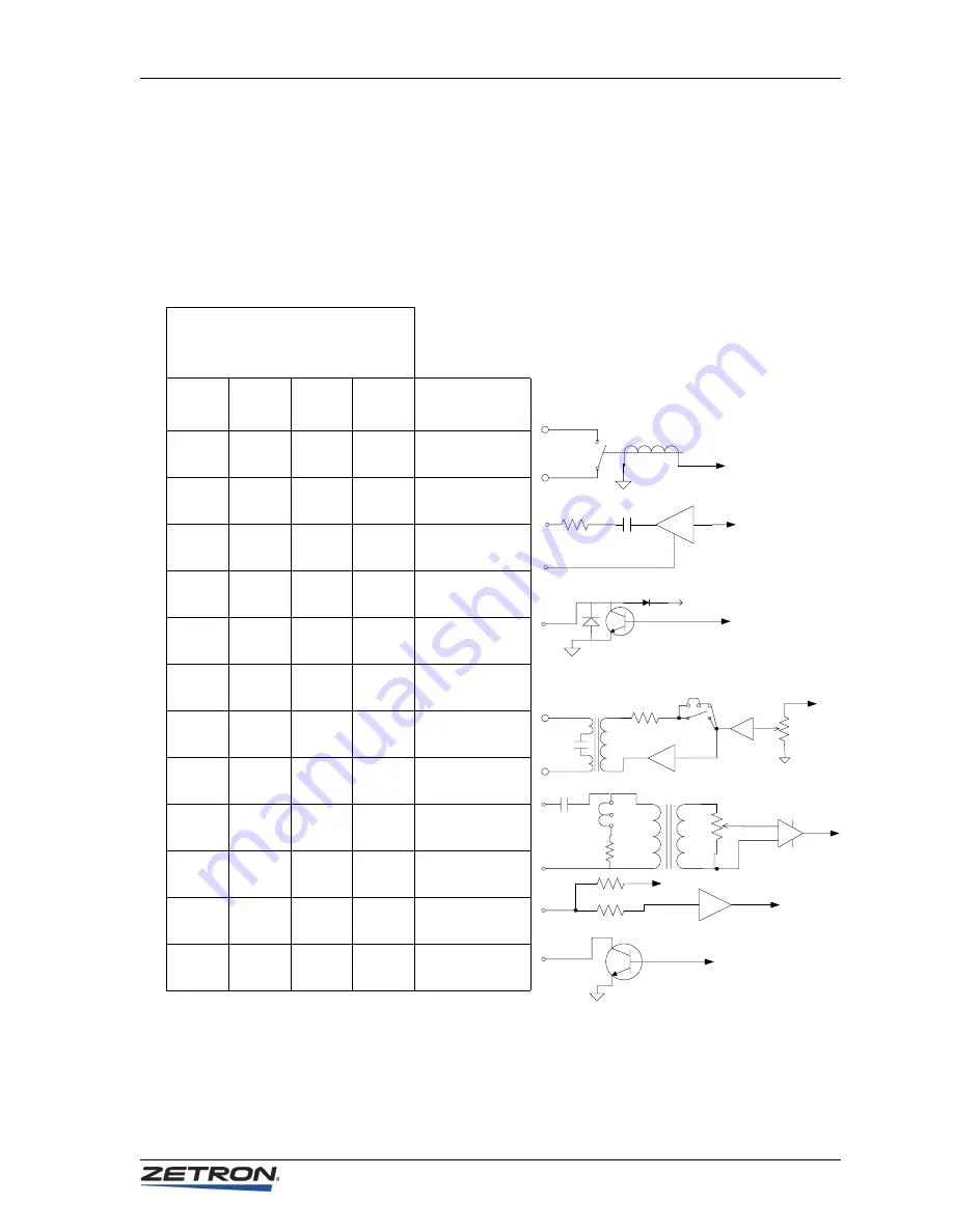
Equivalent Circuits
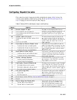
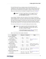
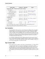
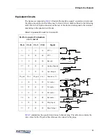
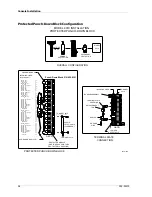
The figures accompanying
illustrate the interface signals’ equivalent circuits and
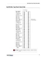
the plug connections on which they may be found. All pin numbers listed in the following
table refer to the 50-pin connectors on the rear of the unit and correspond to the terminal
numbering on the punch-down blocks.
Table 6: Equivalent Circuits for Console I/O
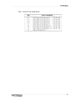
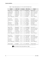
summarizes the signals found on each channel plug. The table also contains the
wire colors for the 25-pair cables often used to connect to the plugs.
2.2uF
600 Ohm
600 Ohm
10K Ohm
2.2 uF
10K Ohm
3.3K Ohm
10K Ohm
+12V
+12V
600 Ohm
10 uF
50-Pin Connector Pin Numbers
J2, J3, and J4
Ch-A
Ch-B
Ch-C
Ch-D
Signal
1
7
13
19
PTT +
26
32
38
44
PTT –
2
8
14
20
Record
27
33
39
45
Analog Ground
3
9
15
21
Aux Output
28 gnd
34 v+
40 gnd
46 v+
Ground or V+
4
10
16
22
Tx Audio +
29
35
41
47
Tx Audio –
5
11
17
23
Rx Audio +
30
36
42
48
Rx Audio –
6
12
18
24
Busy Input
31
37
43
49
Busy Output
Содержание 4010
Страница 1: ...Model 4010 Radio Dispatch Console Installation and Programming 025 9227S ...
Страница 46: ...Console Installation 46 025 9227S ...
Страница 78: ...Option Installation 78 025 9227S ...
Страница 134: ...Appendix D Troubleshooting 134 025 9227S ...

