32
16. 16mm Potentiometers:
a. Before we install the potentiometers (or “pots”) we need to trim some component leads
as short as possible so they don’t puncture the insulation paper and short out against the
bottoms of the pots. The outlines of the pots are drawn on the solder side of the board. Trim
down all the leads that are inside these circles (107). Cut them as short as possible, without
cutting into the solder joints themselves.
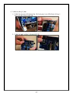
b. Next, break the anti-rotation tabs off of each pot. Use your needle nose pliers and gently
bend the tabs out until they snap off (108). Throw the tabs away.
107
108
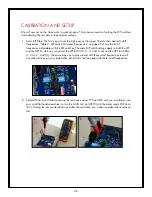
c. There are seven pots in two different values: six 100K pots (VR1-VR6, labeled “B100K”)
and one 500K pot (VR7, labeled “B500K”). Install the 500K pot at VR7 (109). Hold down
the pot from the solder side. Make sure the body of the pot is neatly centered in the round
graphic on the board. Be sure the leads are fully inserted into their holes, then tack-solder in
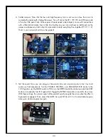
the center pin from the solder side (110). Repeat with the other six pots (111). Double-check
to make sure the pots are lined up properly and the pins are fully seated into their holes,
then go back and finish soldering them in from the component side (112).
109
110
111
112


