35
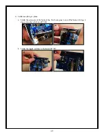
c. Place the solder lug on VR3 (the DEPTH pot) (125). Guide the wire around the power LED
and into the ground hole in the corner of the PCB, near the input jack. Solder in place on the
component side.
125
126
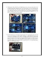
19. Toggle Switches (S3, S4): Remove all the washers and nuts from both toggle switches and set
aside. Place the switches in their places at S3 and S4 (127,128). We’ll solder them in once the
PCB is in the chassis.
127
128
Congratulations!
Your Quaverato PCB is all done. If you are building the MIDI Mod, please consult the MIDI Mod
Assembly Instructions and populate the PCB now.
Don’t try to plug in your Quaverato yet. You still must mount it in its chassis and connect the footswitches
before you can power it up and begin the calibration process. Be of good cheer! You are almost done
with that soldering iron! Then you can go wash up and enjoy a cool drink.


