28
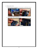
iv. Install the ATmega328-PU microcontroller in its socket. Be careful to align the divot in
the end of the micro with the divot in the end of the socket. If the pins don’t line up easily
with the socket, you may have to gently bend the pins a little closer together by pushing
each side of the chip down on the tabletop. (82,83). Once the pins line up to the socket
holes, push the IC snugly into place (84,85).
82
83
84
85
b. Op-Amp, TL072 (U2, U3): These chips are dual operational amplifiers (op-amps for short),
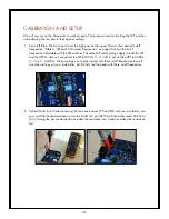
marked TL072, that drive and boost the audio signal. Install these ICs in their locations (86).
You may need to gently flatten the pins down on each side of the chip to get them to fit more
easily into their holes. Notice the divot at one end of the chip. There is a matching shape on
the PCB graphic. Press the op-amps down snugly with your fingertip. Mount the PCB in your
clamp and tack one pin down with solder from the component side. Now flip the board over
and finish soldering the rest of the pins (87).
86
87


