


33
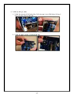
d. Gently bend the potentiometers slightly up-right, until their back is parallel with the PCB
(113).
e. Cut the strip of insulation paper into two strips: 4.5” (11.5cm) and 3.25” (8.5cm). Slide the
strips under the pots to help insulate them from the leads on the PCB (114).
113
114
17. 3mm LEDs: The BYPASS and POWER LEDs are red and the TAP LED is green. We use 9mm
standoffs to place them accurately above the PCB.
a. Insert the leads of a red LED into the open end of a standoff (115). Poke the leads out
through the two holes at the other end (116).
115
116
b. Insert the leads into the LED location on the solder side of the board. The long lead goes into
square pad, otherwise it won’t work! Press down on the LED so the standoff is tight against
the surface of the board. Hold the LED perpendicular to the PCB (118).
117
118