background image

1

2

3

4

D

D

C

C

B

Содержание QUAVERATO

Страница 1: ......

Страница 2: ...THROUGH THEIR PRODUCTS The QUAVERATO SOFTWARE is COVERED BY the Creative Commons Share Alike ATTRIBUTION NON COMMERCIAL license which means you are free to add or build upon THE circuit idea AND THE S...

Страница 3: ...orical Context In the early 1940 s the DeArmond company of Toledo Ohio started manufacturing the very first stand alone effect unit an electro mechanical tremolo How this effect worked was very simple...

Страница 4: ...ably attenuated Optical tremolos create a pulsing or throbbing sound and tend to modulate the signal in a more lopsided manner which tends to be quite pleasing to the ear In a harmonic tremolo circuit...

Страница 5: ...light dependent resistor LDR and a light emitting diode LED The LDR is in series with the audio path When the LED is dark the LDR s resistance is at maximum which is much too high for any audio signa...

Страница 6: ...cquaint you with the parts and their names If anything is missing first double check we double checked before sealing the box at our lab If it s still missing EMAIL US right away at info zeppelindesig...

Страница 7: ...al Purpose 1N4007 1000V 1A D1 D2 D3 3 DI 30 32 LED 3mm Green TAP LED 1 DI 30 36 LED 3mm Red BYPASS LED POWER LED 2 DI 30 52 LED 5mm Green For Optocouplers 2 FA 60 32 Screw Philips Pan Head 6 x 1 4 4 H...

Страница 8: ...2 R15 6 RS 80 50 Resistor 14K R17 R21 2 RS 80 51 Resistor 10K R2 R3 R13 R14 R16 5 RS 80 52 Resistor 18K R18 R22 2 RS 80 54 Resistor 36K R20 R24 2 RS 80 56 Resistor 24K R19 R23 2 RS 80 61 Resistor 100K...

Страница 9: ...P2 MIDI IN U1 U2 U3 Q1 Q2 IC 30 60 U5 PC 10 01 PL 10 10 PL 10 90 VR2 VR7 VR1 VR8 VR9 VR10 RL1 R7 R8 R4 6 R11 12 R15 R17 R21 R2 3 R13 14 R16 R18 R22 R20 R24 R19 R23 R9 R10 R1 SN 30 10 ST 60 39 S1 S2 S...

Страница 10: ...rosin core small diameter good quality We prefer 032 0 8mm Kester brand but most brands will work fine 2 Isopropyl alcohol and cleaning rag 3 Transparent tape or masking tape 4 Solder braid AKA solde...

Страница 11: ...onsists of the following 1 Install the part on the component side of the board by threading the wire leads through the appropriate holes in the board For your convenience the board has silk screen out...

Страница 12: ...each resistor The white graphics on the component side of the board give reference to the part number and value Figure 4 shows the component values and locations and may be easier to read than the gra...

Страница 13: ...he solder side as described above 3 4 5 6 Don t solder any of them until all 24 resistors are installed 3 4 5 6 b Install the 10K resistors R2 R3 R13 R14 R16 These resistors are marked BROWN BLACK BLA...

Страница 14: ...nd the leads on the back f The rest of these resistors will be installed upright on the board 12 Install the 14K resistors R17 R21 marked BROWN YELLOW BLACK RED BROWN Bend the leads g Install the 18K...

Страница 15: ...k Now clip each lead with your flush cutters at the solder joint 18 19 18 19 l Before installing any more components on the circuit board double check the resistance values of each of the installed r...

Страница 16: ...he striped end of the diode goes in the hole with the square pad The lead coming from the non striped end of the diode goes in the round pad WHITE STRIPE SQUARE PAD NO STRIPE ROUND PAD Place the diode...

Страница 17: ...caps are labeled 104 and 22pF caps are labeled 22 Please make sure that you use the correct value in the correct location Ceramic capacitors are not polarized It doesn t matter which lead goes into w...

Страница 18: ...nd bend out its leads 32 33 34 c Electrolytic Capacitors There is one 1uF cap C4 one 10uF cap C15 and one 220uF cap C14 You can read their values on their casings Electrolytic capacitors ARE POLARIZED...

Страница 19: ...reference Figure 4 on page 11 has little red plus signs on the positive pads i Install C4 in its place and bend the leads out 35 ii Install C15 in its place and bend the leads out 36 35 36 iii Instal...

Страница 20: ...er in this kit comes pre programmed with the software needed to make your Quaverato work but you can mod or tweak the software and re program the chip if you are into that sort of thing See the Quaver...

Страница 21: ...d will allow you to control many different parameters of your Quaverato via an external MIDI controller Install the 4 pin header piece in the MIDI IN location in the same manner as the ISP header hold...

Страница 22: ...ink tubing into two equal lengths They both should be about 11 16 17 18mm long 46 47 46 47 b Insert a green 5mm LED don t get them confused with the 3mm LEDs into the end of a piece of heat shrink tub...

Страница 23: ...the same plane as the LED leads 55 54 55 e As you hold the LDR from the outside of the heat shrink carefully heat this side of the tube until it closes around the LDR leads 56 57 While it is still ver...

Страница 24: ...ntended to go On your optocoupler the LED has one long lead and one short lead The long lead of the LED goes into the hole with the square pad Note which side of the optocoupler needs to be up as you...

Страница 25: ...s and snip them flush 68 69 68 69 7 DC Power Jack Press the jack snug to the board and slide it all the way forward toward the edge of the board 70 Double check to make sure it s sitting square to the...

Страница 26: ...ical Place VR10 in its location with the adjustment screw located toward R4 and R5 76 Place VR8 and VR9 in their locations with the adjustment screw toward U1 the big 28 pin chip socket 77 Solder and...

Страница 27: ...e which tells the pedal how to operate This software is open source and published under the creative commons license To learn how to modify the software to make your Quaverato behave differently pleas...

Страница 28: ...5 82 83 84 85 b Op Amp TL072 U2 U3 These chips are dual operational amplifiers op amps for short marked TL072 that drive and boost the audio signal Install these ICs in their locations 86 You may need...

Страница 29: ...e which describes the pin layout on these miniature switches When installing them make sure the labels on the switches line up with the markings on the PCB 90 Hold the switch in place with your finger...

Страница 30: ...5 97 94 95 96 97 14 Hookup Wires The 5 conductor ribbon wire needs to be split into three pieces two 2 wire pieces and one 1 wire piece Slit the wires at one end with your knife and pull them apart 98...

Страница 31: ...install the solder lug 102 103 104 15 Switch Wires Insert one of the 2 wire pieces into the BYPASS SW pads on the component side of the PCB Solder them on the solder side Repeat with the other wire pa...

Страница 32: ...pliers and gently bend the tabs out until they snap off 108 Throw the tabs away 107 108 c There are seven pots in two different values six 100K pots VR1 VR6 labeled B100K and one 500K pot VR7 labeled...

Страница 33: ...ER LEDs are red and the TAP LED is green We use 9mm standoffs to place them accurately above the PCB a Insert the leads of a red LED into the open end of a standoff 115 Poke the leads out through the...

Страница 34: ...ation 119 120 119 120 18 Ground Lug The ground lug electrically connects the chassis to the circuit ground a Solder the single remaining wire to the ground lug tab Bend a little hook in the wire with...

Страница 35: ...eir places at S3 and S4 127 128 We ll solder them in once the PCB is in the chassis 127 128 Congratulations Your Quaverato PCB is all done If you are building the MIDI Mod please consult the MIDI Mod...

Страница 36: ...abel s backing paper when doing this 2 1 2 c Line up all of the label holes with all of the chassis holes 3 Securely tape down just one edge of the label 4 3 4 d Lift up the free side of the label and...

Страница 37: ...wn on the clean flat surface of your table or bench 8 7 8 e Stick the serial number label to the bottom part of the chassis to the right of the power jack cutout 9 10 9 10 2 Install the PCB a With the...

Страница 38: ...4 b Place a washer and a nut on each of the seven pots 15 16 17 Tighten the nuts down with a 10mm socket or a snub nose pliers 18 15 16 17 18 c Thread a nut onto each of the toggle switches 19 Use an...

Страница 39: ...tom nut about half way up on the threaded shaft 22 21 22 b Install the footswitches in the chassis as in the picture with the lugs facing out toward the sides 23 Add a washer and then a nut to each sw...

Страница 40: ...der everything in place a Solder the wire pairs to the footswitches Each wire goes to one of the footswitch lugs it does not matter which one 27 28 27 28 b Solder the toggle switches to the board 29 3...

Страница 41: ...g the knob off the surface of the chassis about 1 8 3 4mm tighten the knob set screw Test to see that the knob stripe lines up nicely with the label markings with the knob turned to both extremes Cont...

Страница 42: ...DIP switch settings apply to both the LPF and the HPF To start out we will set the LPF to 401Hz 1 2 4 off 3 on and the HPF to 600Hz 1 3 on 2 4 off 1 We encourage you to play around with these cutoff...

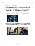
Страница 43: ...power LED D1 and C14 Turn the DEPTH knob fully counterclockwise so the LFO is not pulsing Press the BYPASS foot switch so the red bypass LED is on 4 4 b While measuring the resistance across TP1 and...

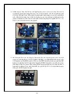
Страница 44: ...gether 9 10 11 12 That s it your jumpers should now be jumped 9 10 11 12 5 Test the sound Now you can plug your Quaverato into your amp and guitar to test it out and make any final adjustments Set the...

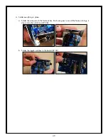
Страница 45: ...ate the trim pots you will need to use some solder wick to remove the solder jumpers Also feel free to play with the DIP switch settings to explore the sonic possibilities of adjusting the crossover f...

Страница 46: ...talled into the bottom chassis 1 Place the 1 4 jacks through the holes in the bottom also align the DC jack to fit through its square hole not behind it You will know the chassis is properly closed wh...

Страница 47: ...mp and prepare to quaver like a leaf in a breeze flutter like my heart when I see my wife throb like my head after a late night Monopoly loss to Colleen For complete operating instructions and an in d...

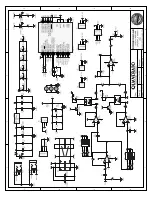
Страница 48: ...1 2 3 4 D D C C B...

Страница 49: ......

Отзывы: