background image


InZennio Z41 

http://www.zennio.com

                                                                     Tecnical Support: 

http://support.zennio.com


85 


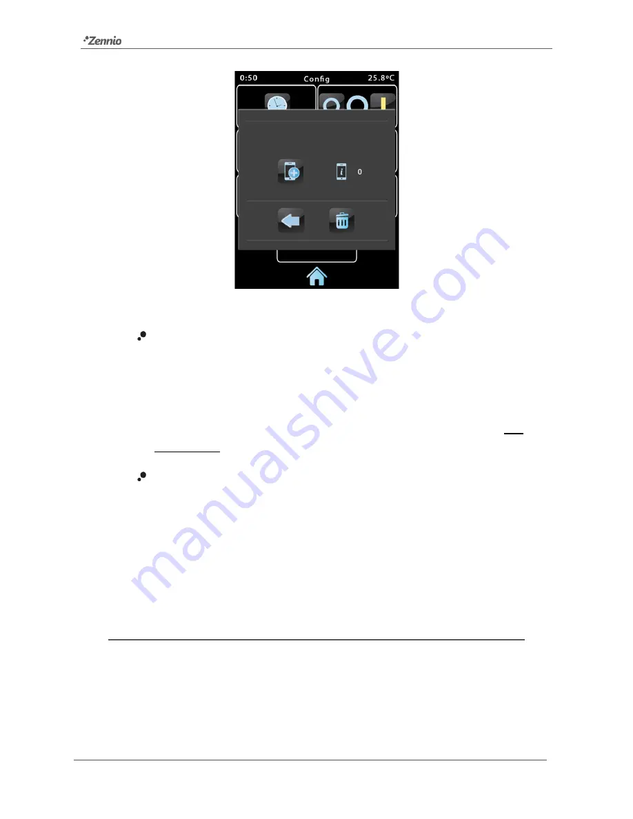
Figure 90 

Device Pairing dialog window


  On a short  press, the Pairing Code Request button sends a Pairing Code 

request, which will be  responded  with an 

alphanumeric key word

  that Z41 

will show on the upper section of the window, unless a communication error 

takes place (in such case, the word “ERROR” will be displayed on the 

screen). The user will be required to enter this key  word  on the remote 

application in order to set the link with Z41.  Note that this process is only 

required once, so the mobile device can register the particular Z41. 

  The indicator on the right shows the 

currently active pairings

 of the device, 

that is, the number of remote applications or devices Z41 remains paired to, 

and from which it can be controlled. The initial value is 0. 

Finally, the lower portion of the window comprises the 

validation button

, which lets 

the user confirm the process and close the pop-up window, and the 

bin button

, which 

(after a long press) deletes all current pairings and clears the pairing counter. 

‘PUSH’ NOTIFICATIONS 

Starting with version 3.3, Z41 incorporates the “push” notification function, which 

consists in notifying the mobile devices (no matter if the remote control application has 

been started or not) about alarm events (see section 3.4.2.5): 

Содержание ZN1VI-TP41C

Страница 1: ...KNX Capacitive Colour Touch Panel USER MANUAL ZN1VI TP41C Application Program Version 3 3 User Manual Version 3 3 _b www zennio com...

Страница 2: ...nese Korean for on screen texts Pairing procedure for remotely controlling the device Replacement of certain icons Parameters for enabling disabling the firmware update function via USB or Ethernet Pa...

Страница 3: ...et to them Interruption of the inactivity timeout counter if a pop up windows is active Unification of the text format and time spacing of labels shown in graphical value monitoring 2 0_a Changes in t...

Страница 4: ...al Purpose Pages 14 2 3 Profile Page 14 2 4 Configuration Page 16 2 5 Backlight 19 2 6 Page Shaping 19 3 ETS Parameterisation 21 3 1 Default Configuration 21 3 2 Main Configuration 24 3 2 1 General 24...

Страница 5: ...button Control 46 3 4 2 4 Climate Control 56 3 4 2 5 Other 64 3 5 Profile Page 80 3 5 1 Configuration 80 3 6 Configuration Page 81 3 6 1 Configuration 81 3 7 Thermostat n 82 ANNEX I Controlling Z41 Re...

Страница 6: ...with various pre set colour patterns and themes Multiple direct action functions fully customisable Control distribution across up to 6 customisable pages Full climate management Programmable timers S...

Страница 7: ...Climate controls RGB controls RGBW controls Energy consumption monitoring Gas Water consumption monitoring Daily timers 48 48 48 48 Weekly timers 16 48 48 48 48 Alarms 8 48 48 48 48 Alarm log Remote...

Страница 8: ...ss o Unsigned integer 8 16 bits o Signed integer 8 16 bits o Scaling percentage o Floating point 16 bits o Scene run save 2 button Controls o Binary icon text number o Enumerated icon text o Unsigned...

Страница 9: ...ek Cyrillic and Hebrew characters 1 3 INSTALLATION Figure 1 shows the connection outline of the InZennio Z41 screen Figure 1 Element Diagram The InZennio Z41 connects to the KNX bus through the built...

Страница 10: ...disconnect and connect the device back avoiding making pressure over the panel in order to perform a new calibration After the connection of the external power supply the screen will blink for an ins...

Страница 11: ...mming mode The programming LED 3 will then light in red On the contrary if this button is held while the device gets connected to the bus Z41 will enter the safe mode In such case the programming LED...

Страница 12: ...latter the connection of a flash memory drive to the USB slot see 5 in Figure 1 through the proper adapter or the connection of an Ethernet network cable see 6 in Figure 1 For further details on the f...

Страница 13: ...e alarms see epigraph g in section 3 4 2 5 within the page while a lock reflects that the access to the page is password protected see section 3 2 2 On the other hand 6 out of the 8 pages are general...

Страница 14: ...the pages automatically distributed or not according to page parameterisation For more details on the box distribution refer to section 2 6 The parameterisable controls for the general purpose pages...

Страница 15: ...on presses or as a feedback on action executions One more possibility is to make these beeps silent alarm beeps will still work Note that the labels of the controls in the Profile page as well as the...

Страница 16: ...the internal time and date from an external device they can also be adjusted if such option has been enabled by parameter directly from the user interface Therefore by pressing this button a set of c...

Страница 17: ...s consumption logs or any other historic logs are not reset to zero in any case such thing takes only place after a firmware download see section 1 3 1 Nevertheless a device reset from ETS does reset...

Страница 18: ...he internal temperature probe This way if the value of the measurement is found to be slightly over or below the actual temperature due to external factors the final user will have the option to set a...

Страница 19: ...ehaviour may differ in case a pop up window is open as well as depending on the configuration set in parameters see section 3 2 1 2 6 PAGE SHAPING Each of the pages of the user interface including Men...

Страница 20: ...InZennio Z41 http www zennio com Tecnical Support http support zennio com 20 Figure 11 Dynamic Distribution of the enabled boxes...

Страница 21: ...ependence of whether they reach the maximum text length allowed by ETS or not Important whenever the device is updated to a new version of the application program from ETS it is also necessary to upda...

Страница 22: ...gh which the value of the current measurement of the built in sensor will be sent to the bus according to the parameterisation see section 3 2 4 General Illumination 1 bit object that upon the recepti...

Страница 23: ...pages of the device see section 2 2 Profile Page which itself will contain one more screen Configuration from which it will be possible to activate and configure the Profile page see section 2 3 Conf...

Страница 24: ...GENERAL The General screen contains the following parameters Figure 14 General Main Configuration Power Supply Voltage lets the integrator specify the particular voltage of the external supply poweri...

Страница 25: ...nal value If the latter is chosen an object named General External temperature will be enabled so that it can be grouped with any other object that sends temperature values Time Date Sending Period wh...

Страница 26: ...he label that will be shown within the configuration pages of the weekly timers see epigraph e in section 3 4 2 5 next to the checkbox that enables disables the sending of the switch off order The def...

Страница 27: ...making password 2 available to users with further privileges while password 1 is assigned to users with fewer privileges The parameters on the Security screen are Security Levels dropdown list for se...

Страница 28: ...d for level 1 Figure 17 Two Security Levels Security Pad Labels parameter consisting in six additional textboxes intended for the customisation of the messages that the device shows or may show when t...

Страница 29: ...re shown Touch Locking dropdown list with the following options 0 Touch enabled 1 Touch disabled default value and 0 Touch disabled 1 Touch enabled Depending on the selection sending one value or anot...

Страница 30: ...bit object If Scene is selected the General Scenes Send object already enabled in the beginning will work as the welcome object In this case the following two parameters come up Scene Number number of...

Страница 31: ...untime from the Configuration page see section 2 4 Sending Period cycle time in tens of a second for sending the value of the measured temperature to the bus This sending is made through the General I...

Страница 32: ...dentify it from the Z41 Update desktop application which may detect other Z41 devices on the same local network provided for performing firmware updates on Z41 through the Ethernet interface Finally t...

Страница 33: ...water gas flow measurements depending on the consumption type Consumption x Energy Volume 4 byte object to be linked to external objects reporting energy consumption measurements or water gas volume...

Страница 34: ...mers For further information about the usage of these objects and about the per channel dimming controls implemented by Z41 please refer to epigraph b in section 3 4 2 5 3 2 8 FIRMWARE UPDATE Figure 2...

Страница 35: ...This password consisting in four numerical figures needs to be set in ETS by the integrator Figure 26 Password Protected Update Note reading the specific user manual of the firmware update process av...

Страница 36: ...ibuted option Yes depending on the number of boxes configured or be displayed as a static 2x4 grid option No See section 2 6 Default Page dropdown list that sets the page Menu or any of the general pu...

Страница 37: ...screens will appear Note figures in this section will show the parameters of a certain page for instance page 1 or a certain box for instance box 1 The parameters for other pages or boxes are totally...

Страница 38: ...ers can access it Yes the page will be protected by password Users will be asked to type the password when trying to access it Two levels No the page will not be protected by password All users can ac...

Страница 39: ...will change The following sections explain the available parameters depending on the visualization type selected 3 4 2 1 INDICATOR Figure 30 Indicator Box Boxes configured as indicators permit impleme...

Страница 40: ...hown when the object receives a 0 Text Off and that to be shown when it becomes 1 Text On Therefore when the device receives the values 0 or 1 through the aforementioned object the box will show one t...

Страница 41: ...ehave analogously to the case of the Binary indicator Text however it will be possible to distinguish up to 6 states configurable through the Enums parameter instead of only two The states will be det...

Страница 42: ...the particular case of the 2 byte floating point indicator the integrator will be shown a text field Float Unit empty by default that permits specifying the measuring units up to 6 characters of the...

Страница 43: ...ws the chronological evolution of the value with higher or lower detail hourly daily weekly monthly see Figure 38 depending on the zoom level set by the user by means of the on screen magnifying glass...

Страница 44: ...hich turns visible as soon as this function is assigned to the box Figure 40 Binary control On the other hand Action permits setting what value will be sent to the bus through the mentioned object and...

Страница 45: ...to user presses by sending a certain numerical value which is required to be specified under Constant value Figure 41 1 byte constant unsigned int Table 3 shows for every available Function the permi...

Страница 46: ...nly send scene execution orders after a short press or if it will be possible in addition to sending execution orders upon short presses to send scene save orders in the case of a long press Figure 42...

Страница 47: ...of a certain status only the final value selected by the user will be sent to the bus to prevent an unnecessary bus traffic due to all the intermediate values On the other hand the Function parameter...

Страница 48: ...parameters available are Action sets the value to be sent on button touches This can be Left 0 Right 1 default or Left 1 Right 0 Text Off and Text On indicative texts that will be shown in the box dep...

Страница 49: ...sets the control box to state j Icon j indicative icon that will be displayed in the box when the status object which gets automatically updated whenever a control order is sent although it may also...

Страница 50: ...tatus object which gets automatically updated whenever a control order is sent although it may also receive values from the bus acquires the numerical value defined in the above parameter e Numerical...

Страница 51: ...2 byte signed int indicator 2 byte float 671088 64 670760 96 Pn Bi 2 byte float control Pn Bi 2 byte float indicator Table 4 Numerical Controls For all the six functions the parameters available are F...

Страница 52: ...s the increase or decrease to be applied to the current value on every long press over the increase or decrease buttons respectively i e the smaller the increment is the more presses will be required...

Страница 53: ...ument Z41 Icon list available at www zennio com g Shutter Control Shutter controls permit sending move up move down stop or step shutter orders to the KNX bus by pressing the buttons in the box In add...

Страница 54: ...as already in movement these orders are interpreted by the actuator as a stop order h Lighting Control The lighting control function permits making use of the two buttons in the box to send orders to...

Страница 55: ...rised dimming step while a stop order value 8 will be sent through the same object as soon as the user releases the button When a long press on the turn off button takes place the object Pn Bi Light D...

Страница 56: ...ows a Setpoint Control This function permits controlling the temperature setpoint of an external thermostat by means of a two button box and of the parameters enabled to that effect Pn Bi Temperature...

Страница 57: ...y higher or lower as the user touches the control buttons On the other hand the permitted temperature setpoints will be delimited by a maximum value and a minimum value defined by the so named paramet...

Страница 58: ...mum offset of 10 Maximum offset of 10 The objects are linked to those from an external thermostat which can be supposed to have a base temperature setpoint of 25 C After the parameter download 1 The f...

Страница 59: ...eceives the value 0 after having the user performed three presses on the increase button therefore after having been sent the value 1 5 to the bus it will happen that on the forth press the value sent...

Страница 60: ...de Box Two communication objects are also enabled the Pn Bi Mode Control control object and the Pn Bi Mode Indicator status object When the user activates the Cool mode the device will send the value...

Страница 61: ...Depending on the mode selected by the user the control object will be sent to the bus a certain value see Table 6 after which the box will display the icon that corresponds to the new mode Additional...

Страница 62: ...a percentage the value of the current fan level which will be represented with a variable icon on the box The parameters available are Action permits setting the increase or decrease actions to one bu...

Страница 63: ...ft Button and Right Button permit selecting the icon that will be displayed inside the buttons of the box Note a list with all the icons available in Z41 can be found in document Z41 Icon list availab...

Страница 64: ...Standby 2 0x002 Economy 3 0x003 Protection 4 0x004 Table 7 Special Modes vs Icon vs Object Value The remaining parameters for this function are Allow Protection Mode this parameter permits including...

Страница 65: ...enabled with their Write and Read flags activated so they can work as control and status objects named Pn Bi Red Channel Pn Bi Green Channel Pn Bi Blue Channel Control orders will consist in sending t...

Страница 66: ...e found in the box The button on the left which is an On Off switch permits commuting between a total absence of light in the three channel and their respective states previous to the switch off The b...

Страница 67: ...which of the four white channels available will be regulated by the box The channel selected here must have been specifically enabled from the White Channel Objects screen see section 3 2 7 under the...

Страница 68: ...ulators shown in the case of the RGB control boxes Figure 70 RGBW Colour Palette c Consumption Monitor This function permits making use of one of the boxes of Z41 as a monitor of energy or water gas c...

Страница 69: ...Consumption x Power Flow depending on the channel configuration Consumption x Energy Volume depending on the channel configuration Consumption x CO2 and Consumption x Cost objects where x is the numbe...

Страница 70: ...ng of the data they receive from the bus so it is entirely at the integrator s choice whether the box will monitor estimations average consumptions real consumptions etc Finally in the pop up window t...

Страница 71: ...timers let the final user program a timed sending of a value to the bus being possible to send binary or scene values according to the parameterisation at a certain time either every day or only once...

Страница 72: ...ect for binary values or through the General Scenes Send object in case of scene values In both cases the Pn Bi Daily Timer Enabling binary object will be available making it possible to disable by se...

Страница 73: ...ry week on the days selected by the user Figure 78 Weekly Timer Box Hence when pressing on the box a window similar to Figure 79 will pop up Figure 79 Weekly Timer Pop Up Window This window contains t...

Страница 74: ...timed sending set by the user By default timed sending is always enabled Note in case of disabling a sending through Pn Bi Weekly Timer Enabling the corresponding box will show the forbidden icon alt...

Страница 75: ...20 95 x 1 C Default value 18 C Maximum Setpoint Value maximum setpoint value the user will be able to set Range 20 95 x 1 C Default value 30 C When a box is configured as a chrono thermostat it looks...

Страница 76: ...ay After that the user should select through controls and the temperature setpoint that will be sent The range of this value is restricted by parameters Minimum Setpoint Value and Maximum Setpoint Val...

Страница 77: ...rough which the timed temperature setpoints will be sent Pn Bi Chrono Thermostat On Off this is the object through which the timed switch off orders will be sent g Alarm Figure 83 Alarm Boxes configur...

Страница 78: ...o alarm state the order of these two events is irrelevant after which the icon will finally turn off Figure 85 Alarm state diagram case of confirmation previous to the alarm end Note whenever an alarm...

Страница 79: ...er object from an alarm box in Z41 where no periodical monitoring has been parameterised and where the value 1 has been set as the alarm value then Z41 will notify an emergency every time a flood take...

Страница 80: ...as the label that will identify them on the screen Note that the Profile page itself can be activated or hidden from the Configuration screen under the Menu tab see section 3 3 1 Figure 86 Configurat...

Страница 81: ...iguration page itself can be activated or hidden from the Configuration screen under the Menu tab see section 3 3 1 Figure 87 Configuration Screen Configuration Page By default the Time Date and Progr...

Страница 82: ...wo more tabs both similar to each other for the parameterisation of these functions independently Under each of the tabs a set of screens Configuration Setpoint etc is provided to define the type of t...

Страница 83: ...rator specifically enables it in ETS through the Remote Control through the Internet parameter from the Ethernet window under the Main Configuration tab see section 3 2 5 Figure 89 Configuration page...

Страница 84: ...g the remote control function itself preventing further pairing does not block the remote access from previously paired devices and that the access to this icon will be anyway subject to the security...

Страница 85: ...so the mobile device can register the particular Z41 The indicator on the right shows the currently active pairings of the device that is the number of remote applications or devices Z41 remains pair...

Страница 86: ...isabled by the operating system of the device depending on the user settings through messages similar to the following figure and according to the label assigned to the involved alarm box Figure 91 Pu...

Страница 87: ...cal Support http support zennio com 87 REMOTE APPLICATIONS For instructions on configuring and using the available remote applications please refer to the Z41 Remote specific document available at the...

Страница 88: ...ction 1 Light Display 6 1 Bit I C W DPT_Switch 0 1 General Touch Lock 0 Touch disabled 1 Touch enabled 1 Bit I C W DPT_Switch 0 1 General Touch Lock 0 Touch enabled 1 Touch disabled 7 1 Bit O C T R DP...

Страница 89: ...BX 2 byte Signed Int Indicator 32768 32767 1 Byte I C W U DPT_HVACMode 1 Comfort 2 Standby 3 Economy 4 Protection PX BX 2 byte Unsigned Int Indicator 0 65535 1 Byte I O C T R W U DPT_Scaling 0 100 PX...

Страница 90: ...Value 1 Bit O C T R DPT_Step 0 1 PX BX Light On Off 0 Off 1 On 1 Bit O C T R DPT_Heat_Cool 0 1 PX BX Move Shutter 0 Up 1 Down 1 Byte O C T R DPT_HVACContrMode 0 Auto 1 Heat 3 Cool 9 Fan 14 Dry PX BX E...

Страница 91: ...rotection TX Special Mode 1 byte HVAC Mode 155 182 1 Bit I C W DPT_Trigger 0 1 TX Special Mode comfort 0 Off 1 On 1 Bit I C W DPT_Switch 0 1 TX Special Mode comfort 0 Nothing 1 Trigger 156 183 1 Bit I...

Страница 92: ...0 1 TX On Off 0 Off 1 On 172 199 1 Bit O C T R DPT_Switch 0 1 TX On Off Status 0 Off 1 On 173 200 1 Bit O C T R DPT_Switch 0 1 TX Control Variable Cool PI Control PWM 1 Bit O C T R DPT_Switch 0 1 TX...

Страница 93: ...mber Size I O Flags Data Type DPT Functional range Name Function 209 213 217 221 225 229 2 Bytes I C W Currency non standardized datapoint type 670760 00 670760 00 Consumption X Cost Local Currency 23...

Страница 94: ...d us your inquiries about Zennio devices http support zennio com Zennio Avance y Tecnolog a S L C R o Jarama 132 Nave P 8 11 45007 Toledo Spain Tel 34 925 232 002 Fax 34 925 337 310 www zennio com inf...

Отзывы: